
“In regards to MT ferrule geometry measurements, Minus Coplanarity (or Minus-Side Coplanarity) is one way to describe how “flat” or “co-planar” an array of fibers is. To ensure minimum optical performance requirements of the telecom world, it is important to ensure that all fibers in a mated pair of connectors will have good contact. It is intuitive that if all fibers of both ferrules are exactly on the same horizontal plane, then all fibers will likely mate well when connected.
However, as anyone who has ever tried to polish an MT ferrule knows, it is virtually impossible to polish an array of fibers to EXACTLY the same heights. There will always be some deviation in height between fibers in the array. But, when the fibers and ferrule are mated and under load, they undergo a degree of compression/distortion that allows for sufficient fiber-to-fiber contact to be achieved, as long as the fiber height variation is not TOO much.
How much fiber height variation is “too much”? This is (among other characteristics) what the standards bodies attempt to define (see IEC 61755-3-31:2015). Originally, the fiber height variation specifications set forth by IEC involved only the max-min heights of all fibers and the height differences between adjacent fibers. Recently, Minus Coplanarity was added to the specification.
Minus Coplanarity is simply the distance between the lowest fiber and the “best-fit plane” through the array of fibers (also called the “fiber line”). It is a measure of fiber height variation within an array of fibers. A lower number is better, with a value of “0” indicating the theoretical ideal – all fibers are EXACTLY the same height.
The best-fit plane is a line through the array of fiber protrusions calculated by using the mathematical “least square method.” Think of it as a straight line through the array which is the best representation of all heights. The least-square method is high-school math and not extremely complicated, but it is exactly the same formula used in Excel graphs when you add a linear trendline through data points. To visualize Minus Coplanarity, it is much easier to use an Excel graph than to use a mathematical formula – so that’s what we’ll do.
Let’s say I have a 12-f MT ferrule with the following fiber heights:
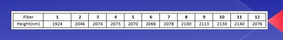
I can graph these points in a simple Excel bar graph and see a visual representation of the array profile.
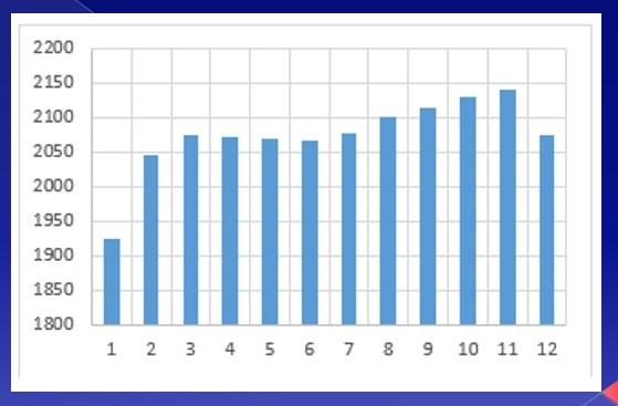
If I add a linear trendline in my Excel graph, I see the “least square method” best-fit line:
Fiber #1 is my lowest fiber, with a height of 1924. My Minus Coplanarity is simply the difference between Fiber #1 and the point on the best-fit line (the trendline) directly above it. In this case, that point is 2012 units, so my Minus Coplanarity value is 88.
Incidentally, the “Minus” of the “Minus Coplanarity” term is simply because we are measuring from the best-fit line down to the lowest fiber. If we were to measure from the best-fit line up to the highest fiber, I guess it would be called “Plus Coplanarity.”
Now that we know what Minus Coplanarity is, what can we do if our products fail to meet this industry specification? Unfortunately, there is no one answer to that question, since results vary significantly depending on your supplier of materials (ferrules and fiber), polishing consumables (lapping films or slurries) and, mostly, on your polishing process (pressures, speeds, and times).
However, one generalization that DOES seem to hold true is that fiber height variation usually increases as overall fiber heights increase. That is, the lower your overall fiber height, the lower your fiber variation (and thus Minus Coplanarity) will be and vice-versa. Thus, if you are having difficulty meeting Minus Coplanarity specifications, consider adjusting your process to lower the overall fiber heights across the array. (Usually, this is a relatively simple adjustment that requires minimal changes to only one step of the existing polishing process.)
If you prefer to keep overall fiber heights high – but still struggle to meet Minus Coplanarity specifications – you’ll likely need to address the phenomenon of “profile rounding” where the edge fibers (fibers #1 and #12 in a 12-f array) typically have the largest difference in heights from their adjacent fibers. Such variation is usually the major contributing factor to poor Minus Coplanarity measurements. Improving the heights of the edge fibers, while maintaining the heights of the remaining fibers in the array, will likely require much more comprehensive and complicated changes to your polishing process.