
How can you adjust your APC polishing process to modify characteristics of the geometry and achieve consistent accuracy?
APC polishing issues could derive from problems with mechanics (materials or equipment) or the polishing process itself. When developing a polishing process, the initial goal is to achieve consistency in geometry results (namely Radius, Angle/Apex, and Key Error), regardless of values (passing or failing of any specifications).
If you don’t see consistent results, it’s likely the variation is due to mechanical/equipment problems such as worn polishing fixtures, uneven rubber pad hardness, etc. After achieving result stability, it’s a simple matter to make process adjustments (namely pressure, rubber pad hardness, film abrasive size) to achieve desired results.
Polishing step ferrules: Angle cutting
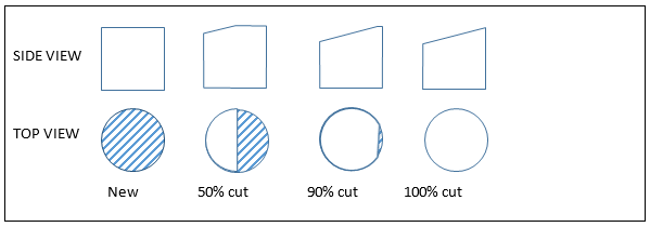
If the step ferrules are not pre-angled, you must, of course, create the angle as part of the polishing process. A good general rule-of-thumb is to aim to have the angle cut all the way across the surface before starting the 1-micron step in the polishing process. Briefly, this often means increasing polishing time or using a more aggressive lapping film in the early polishing steps until the angle is cut all the way across the ferrule surface.
To be clear, the goal is to have the angle cut completely across the ferrule surface before starting the 1um step in your APC polishing process (which is typically the second-to-last step of the process, followed by a Final Polish step).
For a typical 4-step process (16um SC, 5um D, 1um D, Final), I would recommend the following:
- You can increase Step 1’s polishing time until the angle is cut "nearly" all the way across the ferrule surface (say, 70-90%). I can’t offer a specific time recommendation – you would need to determine the optimal time by running Step 1 (typically 16um SC) in increments of 10 seconds. Carefully observe the angle until it has been cut fully.
- Use the second step (typically 5um D film) to continue cutting the angle. The goal is to use only as much time as needed to complete the angle cut across the surface – you don’t want to remove more material than necessary.
- Before starting Step 3, operators must verify that the angle is 100% cut across the surface. If not, they need to add more polishing time to preceding steps, replace the lapping film more frequently, or use more aggressive films (larger abrasive sizes). As a very general rule-of-thumb, if any cycle of the process requires more than 90 seconds of polishing time, you should consider replacing existing films with more aggressive film sizes.
Quick troubleshooting checklist for common APC polishing issues
Whether you’re using step ferrules or conical ferrules, you may have problems achieving consistent results for the 4 basic geometric characteristics – Radius, Angle/Apex, and Key Error – that are relevant to the APC polishing process. The following paragraphs offer troubleshooting tips to overcome common polishing issues.
Equipment checks:
- Rubber pads – If the pads are more than 6 months old, they may show uneven wear. This wear will negatively affect Radius and Apex/Angle results. The replacement schedule is dependent upon use. It is best determined by monitoring Radius and Apex statistics, and replacing rubber pads when values approach control limits. For time-based replacement schedules, I’d recommend every 6 months for moderate-to-heavy use and no longer than 1 year for low-to-moderate use.
- The fixture – Holes in the fixture will wear out over time (generally 3 to 5 years), which can impact parameters (mostly Angle/Apex). Pin gauges can be used to monitor hole diameters, but since wear is often not symmetrical, it’s difficult to quantify hole roundness/ovality. Often, the best way to verify that hole-wear is still acceptable is to return the plate to the manufacturer for measurement or try a new "loaner" fixture and see if results improve significantly.
- Plastic clips in the polishing fixture – These can wear out or break and should be replaced periodically. Also, operators should always ensure connectors click into place properly.
Troubleshooting tips specific to Radius:
If your values vary too much, this could indicate that:
- Ferrules are not protruding equally from the polishing fixture, resulting in each ferrule receiving a varying amount of pressure during polishing. Possible causes include:
- The ferrules are at different heights in the connectors. This is unlikely if you’re using a good quality connector, but it is possible.
- The ferrules are contaminated and cannot protrude fully from the fixture holes. This is common if the ferrule OD is contaminated with epoxy.
- The fixture is damaged or worn, and ferrules protrude at different heights. This happens when the plastic clips are broken or damaged.
- The rubber pad durometer is not constant. Possible causes include:
- The rubber pads are old and need to be replaced. Pad durometer does change over time and use. As noted earlier, pads should be replaced every 6 months (1 year at most).
- The rubber pads are not designed for polishing. This issue occurs when pads are purchased from a non-fiber polishing source and do not have needed durometer consistency across the entire polishing surface.
- Operators are using the wrong durometer rubber pads when polishing. This often happens when pads are not easily identifiable and/or operators are not properly trained.
Troubleshooting tips specific to Key Error:
If your values are not within standard deviation, possible causes include:
- The interferometer adapter for the connector housing (not for the ferrules) does not hold the connector housing properly. This can happen when the adapter is old, because the metal parts will wear over time. Make sure the connector housing is properly inserted into the adapter.
- Not using a connector housing adapter on the interferometer. This is a must for APCs. If it’s missing, all Angle, Apex, and Key Error values will be invalid.
- The ferrule is rotating within the connector after polish. Because the spring is somewhat compressed during polishing, the ferrule is pushed back from its seat in the connector body. Typically these connector parts are plastic and do not offer exact tolerances. Sometimes they hold the ferrule in a slightly different rotational position than when polishing. You can try pushing down on the ferrule several times to compress the spring a bit, so it will settle within the connector. Then re-measure and see if the Apex and Angle values have improved.
- The fixture keying is worn. This can happen if the keying is made of plastic, and the fixture is old. We recommend you replace these parts, if possible.
Troubleshooting tips specific to Angle and Apex Offset:
Key Error, Angle, and Apex are all related. If you know any two of these geometric characteristics, you can mathematically calculate the third. For this reason, the Key Error causes above also can relate to Angle and Apex values. Additional potential causes of Angle and Apex failure include:
- APC ferrule come in one of two ferrule-tip shapes: "Step" or "Conical". With Step ferrules, the angle is easier to control, as the ferrule tip (where the angle is being cut into) is a cylindrical shape—–which means regardless of how much you polish / how much material is removed, the "footprint" of the polished surface remains constant. With Conical ferrules, because the ferrule tip is a conical shape, the footprint gets larger and larger the more we polish / remove material. The alters the angle and radius as we polish more and more, and makes angle control / process development more difficult than step ferrules.
- Step ferrules should be polished using an 8.0 degree APC polishing fixture.
- As long as you are SURE you cut ALL THE WAY across the surface of a Step Ferrule when creating the angle, then the measured angle values should remain constant, regardless of how much you polish. The measured angle values can then only be adjusted by making changes to Radius (increasing or decreasing polishing pressure, or using a different durometer rubber pad). Increasing radius will increase measured angle value, and vice-versa.
- In terms of angle value control, Step ferrules are easier and preferred—-however, they are usually more expensive to purchase.
- Conical ferrules should be polished using an 8.2 degree polishing fixture (this additional angle compensates for smaller footprint on the tip of the Conical ferrules resulting in smaller measured angles).
- The more you polish a conical ferrule, the more the measured angle and radius values will change. Be sure to cut the angle ALL the way across the flat surface.
- If your polishing process results in angle values that are not acceptable, and you don’t know if you should increase or decrease your polishing times—simply re-polish a fixture’s-worth of ferrule and observe the angle change. For example: if you are seeing consistently small angles, repolish and measure: if the angle values increase, then you know you need add more time / steps to your process. If angle values decrease, you have polished too much and need to back off on time / steps.
- Step ferrules should be polished using an 8.0 degree APC polishing fixture.
- The fixture hole IDs are worn or oversized. This is common in plates that are 3 to 5 years old (and older). You can check this with pin gauges or send the plate back to the manufacturer to check tolerances.
- The rubber pad durometer is not constant due to wear. Again, be sure to replace rubber pads every 6 months (1 year at most).
Do you have a specific issue regarding your APC polishing process?
We’re here to help! Send us your question, and we’ll do our best to provide nuts-and-bolts guidance. Fiber Optic Center is committed to helping you manufacture the best fiber optic cable assemblies possible.
Fiber Optic Center is a resource for questions on this and all technical subjects. AskFOC can be found at: https://focenter.com/blog/category/askfoc and the Fiber Optic Center technical experts will answer your questions here.