
Published 10.6.15 in the IWCS Proceedings from the 64th International Cable & Connectivity Symposium (2015) by Wayne Kachmar, President Technical Horsepower Consulting LLC. with Fiber Optic Center, Inc.
Abstract
As the optical fiber and cable industry unfolded, several terms were coined to describe specific properties that were new and different from conventional wire processing. The term “Loose Tight Buffer” has been used to define both a specific property as well as a product problem resulting in different definitions and requirements for a type of optical cable. The time is past due to define a loose tight buffer and how to measure it. This paper proposes definitions of various tight buffer requirements based upon end uses. Termination methods and various environments that such cables and terminations are expected to function in are proposed. The use of existing test criteria and results shows a great sensitivity to both tools and techniques and also shows a great need for standardized tests and test results interpretation. This paper will also propose a set of characteristics based upon generic use of these buffered assemblies such as connection type, environment and tool type. A series of repeatable test methods, measurements, and characteristics for “Loose Tight Buffer, products” will be proposed. Sources of error based upon legacy failures of loose tight buffer cables such as epoxy wicking and buffer shrinkage will be cited.
Keywords: loose buffer; tight buffer; tightbound; strippable; termination; standards; test method; wicking; epoxy
Introduction
As the optical fiber and cable industry unfolded, several terms were coined to describe specific properties that were new and different from conventional wire processing. One of those that stayed around was the term “Loose Tight Buffer” Over the past fifteen to 20 years the term was used to define both a specific property as well as a product problem. This resulted in many different definitions and a broad set of requirements for a type of optical cable. As a result that has meant many different products to many different users. As we move forward the time is past due to create a definition of what exactly is a loose tight buffer and how is it measured. This paper proposes that we define the various tight buffer requirements based upon end uses such as termination with an epoxy polish connector, a fusion splice termination and mechanical field splice connectors. Also the various environments that such cables and terminations are expected to function in, are also in need of clearer definition.
Why Loose Tight Buffer?
As the methods of termination and interconnection continued to evolve, two generic methods of cable design evolved. The most common design was a gel filled loose tube which initially contained only one optical waveguide per tube but could contain many tubes (for multi-fiber cables), and a very robust simplex cable design commonly known as tight buffer. (Also referred to as tight bound.). The loose tube design needed a termination enclosure such as a splice case or termination rack. Initially these were fusion spliced, separated or furcated into individual tubes for termination. For low count optical cables the alternative was an insulation or “buffer” to make the 125 / 250um fiber more resistant to handling and termination. A 900um standard emerged shortly after the SMA optical connector was standardized. This allowed for a solid epoxy bond to an engineering plastic and the glass optical waveguide making a robust termination that could be handled many times with little chance of breakage.
Other methods of termination included fusion splicing as well as mechanical splices. Many of these methods evolved to incorporate methods to estimate the splice loss prior to permanently sealing the splice. One such is the use of local injection and detection, (LID). Due to the need to access optical power thru the optical waveguide, coating removal of the buffer for some distance beyond the splice was required. Typically this occurred in a connector at one end and a fusion splice at the other end. Tight buffer cables now needed to have a removable buffer layer in order to be compatible with such termination systems. These splices were also placed in housings where the amount of space for slack storage was minimal and a 900 um coated fiber takes up 13 times the amount of space compared to a 250um coated fiber. For one fiber this is not a significant issue but place 24 or 72 or 144 fibers in a splice case or rack and the difference is significant.
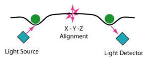
Figure 1. Diagram of local injection and Detection system
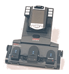
Figure 2. Fusion splicer equipped with LID
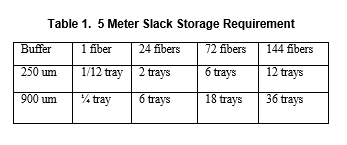
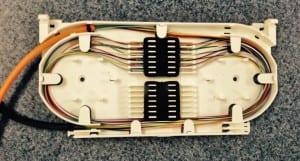
Figure 3. Splice tray
A second reason to create a loose close fitting buffer is specialty fibers which are far more sensitive to mechanical stresses. These came on the scene in uses that required mechanical protection and flexibility, making a rigid loose tube design unacceptable. These fibers may be as small as 60um cladding with a 150um coating or as large as 1mm cladding and 1.4mm coating. In each case the reasons for being able to strip off a coating related to the specific application.
Items such as splicing and splice slack storage were common needs and in many cases large scale field installers using existing equipment for fusion splicing and mechanical field connector termination needed to have a standard medium (size coating) to terminate and train to.
Enter the Loose Tight Buffer
The logical evolution to a removable (loose) tight buffer followed. Due to the varying reasons and lengths of tight buffer removal required, many different specifications propagated. In some cases the buffer was nothing more than a very small loose buffer using a hard engineering material such as nylon that was easily removed using existing loose tube tools. In other cases the lack of excess length control and mechanical robustness made this design limited in usefulness. One area of concern was that in optical waveguide connector termination any gap between the buffer and coating would act as a wicking agent for epoxy to migrate from the connector up through the interstitial space and into the flexible cable. This would almost always cause a fiber break just outside of the cable connector interface. As a result many cable specifications called out no gap between the acrylate coating and the buffer material, while also requiring a strip ability of from 2 to 10 cm.
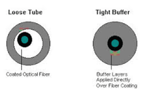
Figure 4. Loose tube / Tight Buffer
Many of the field installable connectors rely on the tight buffer to provide mechanical stress free strain relief of the optical fiber in the ferrule. The presence of lubricants and or a gap can cause the connector performance to degrade. With the proliferation of manufacturers of both cables and field connectors it is almost impossible to develop a matrix of all possible test combinations. Therefore, a series of standard definitions and categories of loose tight buffer will be needed to insure that field connectors are compatible with the type of buffer from multiple cablers.
As terminations improved and thermal performance evolved many manufacturers of tight buffer cables had difficulty maintaining the appropriate stress levels between the coated fiber and the buffer materials. This was exacerbated with the movement to PVC and Low Smoke Zero Halogen buffer materials which were generally softer (< 75A shore hardness). Suddenly, with many different applications for removable buffers, the proliferation of test methods and strip lengths increased exponentially. This leaves us today with a myriad of different requirements and test methods without a single standard to define the category.
Adding to the Confusion
As these new test specifications multiplied so did the tools and methods to strip the buffer. Since in many cases no specific tool was specified, various methods of testing strip ability proliferated.
These included shearing cutters, guillotine types and thermal types using several different manufacturers’ tools. Another variable was the number of passes that are able to be used to strip off the required amount of buffer material.
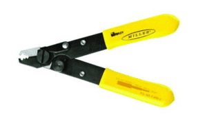
Figure 5. Shearing type stripping tool
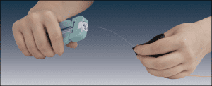
Figure 6. Guillotine type stripping tool
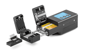
Figure 7. Thermal stripper
The Fibers and Buffers Evolve
In order to meet the end user requirements, many methods of over coating the acrylate coating with lubricants such as talc or other lubricants came into use. Unfortunately some of the lubricants such as flouropolymers were extremely difficult to clean prior to termination. This resulted in poor bonding between optical waveguide and ferrules. Also powders such as talc can contaminate the work area. As a result, applications that require specific environmental performance such as extended temperature ranges and certain chemical resistance also caused other issues in performance. Some of the specific areas of concern were epoxy bonding, buffer materials compatibility and shrinkage of the buffer.
Categories and Methods
The following are a user based proposal to determine categories of loose tight buffer materials:
- Micro Loose tube – A hard engineering polymer loosely surrounding a coated optical waveguide where the gap is equal to ½ the coated optical waveguide diameter or less and there is no interstitial material between the coated optical fiber and the buffer tube.
- Removable tight buffer – A buffer where the gap is not visible under 100 power magnification, no interstitial material defined as loose powder or liquid is used and at least 50cm of material can be removed with one circular cut.
- Filled removable tight buffer – A buffer where the gap is not visible under 100 power magnification, interstitial material defined as loose powder or liquid is used and at least 50cm of material can be removed with one circular cut. The materials are such that over temperature and humidity ranges specified for transport and operation the interstitial material does not chemically interact with either the optical fiber coating or the buffer material over the lifetime of the product. This includes any material weight gain or swelling.
- Strippable tight buffer – A buffer where the gap is not visible under 100 power magnification, no interstitial material defined as loose powder or liquid is used and at least 10 cm of material can be removed with one circular cut.
- Filled strippable tight buffer – A buffer where the gap is not visible under 100 power magnification, interstitial material defined as loose powder or liquid is used and at least 10 cm of material can be removed with one circular cut. The materials are such that over temperature and humidity ranges specified for transport and operation, the interstitial material does not chemically interact with either the optical fiber coating or the buffer material over the lifetime of the product. This includes any material weight gain or swelling.
- Semi tight buffer - A buffer where the gap is not visible under 100 power magnification, no interstitial material defined as loose powder or liquid is used and at least 10 cm of material can be removed with up to 3 circular cuts.
Testing Methods
Presently, any of a number of different tools are in use to remove buffers. They fall into three broad categories: shearing blades, these are similar to the conventional strippers used for fine wire stripping and are made by a number of different manufacturers. They are characterized by a shearing action caused by displaced parallel blades that rely on the materials lower yield to separate the small areas of buffer not captured by the right angle blades. The second type of tools use parallel blades that meet with a predrilled hole sized for the optical fiber coating size. They typically cut almost all the buffer material equally and leave no thicker areas of material to break off during the removal pull. One concern with these tools is blade wear can be rapid and significant making their repeatability poor. The third type of tools use some variant of both the shearing or guillotine styles and a thermal heater to soften the material and make it more compliant in removal. These type tools which make stripping easier are becoming more common in the field but differences in designs and coating materials make them an unlikely candidate for standardized testing.
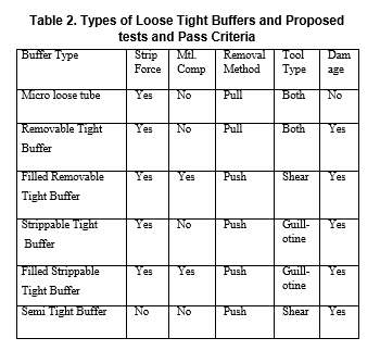
It is worth noting that all three types are in widespread field and factory use. Many large users of optical fiber cables have standardized on one of these types. It is important that a repeatable test method be developed that all cable manufacturers and their customers can use to verify performance and allow multiple vendors of cable to compete with equal performance parameters. Below is a table showing the proposed categories and tool types for a proposed test methodology.
Test Methodology
In order to provide a repeatable and reliable test method we need to provide a set of standard easily reproducible test methods. Selection of a tool(s) from one or more category should define tool condition (i.e. blade sharpness under magnification) as well as the environment and stripping conditions. Questions such as, do we use of the tool to push the buffer off the fiber or to use hand pressure to slide the buffer material by pulling the cut buffer need to be defined. (It is likely that depending on the categories such as length removed and whether there is gel present, different methods by category will be chosen.)
Interpretation of Test Results
In the past standard strip testing of tight buffer fibers has used two criteria as pass fail. These are related to the absolute strip force exerted on the optical fiber when in the act of stripping and secondly, the length of material that can be stripped in one action. As can be seen from the table above, there are several additional properties that must be taken into consideration. These include tool type, microscopic damage to the coating caused by the stripping action, temperature conditioning of the buffered fiber prior to testing, method of pushing or pulling the buffer off and clean ability of the coated and bare fiber post stripping operation.
Conclusions
Based upon the existing and expanded use of strippable tight buffers for a number of applications, specific tight buffer standards need to be developed to allow cable manufacturers to develop and test this family of cables to a common set of standards. Definition of these additional properties will allow uniform development of termination products that take advantage of these defined properties. Basically we need to classify a new cable category and allow both cable manufacturers and termination manufacturers the ability to use the design advantages of a common set of properties.
References
[1] TIA 455A Fiber Optic Test Procedures
[2] Telcordia GR-409-core Issue 2
[3] Telcordia GR-409-core Issue 4
[4] ITU 657.A 2009-11
[5] Verizon TPR 9430
[6] Gye-Tae Moon and Sun-Ae Shin, Development of Re-Usable Super-Innovated (Simple Access-SC) for Quick Installation, IWCS proceedings 2012
[7] Lawrence B. Ingram, Benefits of standards for Wire and Cable Products, IWCS Proceedings 2012
[8] Figure 1. diagram of local injection and Detection system: http://www.thefoa.org/tech/ref/termination/lid.jpg
[9] Figure 2. Fusion splicer equipped with LID: http://www.aurora-optics.com/images/altimax_3.jpg
[10] Figure 3. Splice tray: http://www.fibercommsolutions.com/fiber_optic_splice_trays
[11] Figure 4. Loose tube / Tight Buffer: https://encrypted-tbn2.gstatic.com/imagesq=tbn:ANd9GcRLSzWO4Zpiq5JQmMyFWydSKw2C_NtwMKDihFuqCKYCA4XrDDgqqA
[12] Figure 5. Shearing type stripping tool:
http://www.techni-tool.com/680IE0677?gclid=CNH-q_6HoscCFdYSHwodJ6cJLw&ef_id=VPKENAAAAea00QWQ:20150811221944:s
[13] Figure 6. Guillotine type stripping tool:
[14] Figure 7: Thermal stripper: http://www.signamax.com/optical-fiber-systems/475