
Measuring the insertion loss of a Single Mode jumper would seem to be a simple matter but there are a few complications to consider.
Insertion Loss is a relative measure, it’s the reduction in power when an additional passive element is added to an optical circuit. So, measuring insertion loss is a two-part process - Measure the power coming through a reference path, then power after the DUT has been inserted. The difference is IL.
The loss of an unmated connector can be mathematically estimated but it cannot be measured, only a connection, with a mated pair of connectors, can be measured.
In practical measurement setups, test cables are used to deliver (and sometimes collect) the light to (from) the Device Under Test. So, the quality of these test cables has a direct bearing of the IL reported for the DUT, as the test cable is always part of the connection measured. Unfortunately, it’s not possible in any meaningful way to divide up the measured test connector/DUT connector loss and assign some part of the loss to the test cable and the rest to the DUT. If the test connector were perfect, in every detail, then all loss could then be attributed to the DUT, but no fiber optic cable is perfect, all connectors introduce some loss however small, including test cables.
A good part of the loss across the connection is due to a mismatch of one or more geometrical parameters of the connectors. Consider “Lateral Core Offset” where the fiber core is not perfectly concentric with the ferrule. If mating connectors have a different offset, or offset in a different direction, some light will be directed into the cladding and lost. This offset can be due to a fiber in which the core is not centered, poor ferrules with fiber holes that are not concentric or poor assembly where debris is pushing the fiber to one side of the ferrule hole. For a single-mode connection, an offset of 0.3 microns will produce a loss of about 0.4 dB
An important aspect of this offset loss across a pair of connectors is that it’s not a simple scalar quantity, it depends on the direction of the offset. If offsets are of a similar degree and direction, the cores will match up and the loss could be quite small, but oriented in the opposite direction produces a high loss.
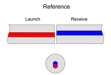
This directional effect can produce some disturbing results. In a dual test cable measurement, if the launch and receive fibers have offsets in opposite directions, the reference path (when they would be connected together) will have significant loss.
Drawing 1. REFERENCE
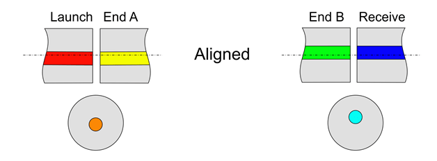
Subsequently, a DUT could be connected between these connectors, who’s offsets (on either end) match those of the test cables to which they are connected. Measured power could now be higher than the reference power. The measurement of this DUT will show negative loss or gain, which is clearly impossible.
Drawing 2. NEGATIVE IL
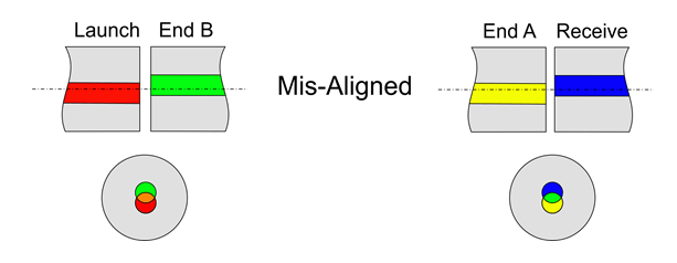
Swapping the DUT around, so both ends are now badly mismatched with the test cables will show a significant loss. Only if the test connectors are perfect, can this situation be avoided. Good quality test cables should be ordered or made and they should be tested for geometry and loss before use and periodically inspected for wear and scratches.
Drawing 3. HIGH LOSS
ADDITIONAL FOC TEST ARTICLES:
- Testing Tips: enhance your process, your results, and your fiber optic cable assemblies
- How to accurately measure IL/RL – This article discusses why it’s important to measure Insertion Loss and Return Loss and how to accurately measure IL/RL. Plus, I offer specific advice regarding whether to use a mandrel wrap, index matching gel, or Optical Time Domain Reflectometer (OTDR) when measuring RL.
- What causes poor IL/RL? – In this nuts-and-bolts discussion, Dan Rocheleau and I address multiple production issues that can cause poor Insertion Loss and Return Loss, along with specific recommendations to remedy the issues.
- Insertion Loss measurement, not a trivial task – If your production facility is new, should you make your own launch jumpers? This might not be a good idea, at least initially. Also, did you know that launch jumpers should use the same fiber type, not just the same size? Here at FOC, we have seen problems mating bend-insensitive fiber to the regular type. You’ll get even more tips in this article.
- Encircled flux – a relatively non-technical overview – The IEC 61280-4-1 Standard sets out to define the distribution of light (flux) at the launch into the device under test. “Encircled flux” is a rather grand way of saying the amount of light inside each circle of a given size within the core. This article addresses why the standard regarding flux is important and how to get consistent EF-compliant measurements.
- Is Bi-Directional testing the silver bullet to cut all your optical testing time in half? – Many cable assembly houses look to Bi-Directional testing as a time savings. However, some do not accurately use this test method. Hint: This test requires the use of a launch AND a receive cable, so when light is shot in one direction there is a launch, and when it’s shot in the opposite direction there is also a launch. Read on to see if you need to adjust your test method to fully utilize the Bi-Directional feature.
- Test cables don’t last forever: How to assess quality, condition, usage limit, and replacement schedule - Provides guidelines to implement procedures to assess the condition of test cables, track usage, and create a reasonable replacement schedule.
- Patch cord gain: Shedding light on this perplexing issue - Discussion on the measurement method to determine how some patch cords show ‘gain.
- Which passive component tester to purchase? Start by answering 7 basic questions to get correctly configured fiber optic test equipment - 7 foundational questions. This will help prepare you to order a PCT with the right test set configuration for your fiber optic product.
Additional resources from the FOC team include:
- View Test Technical Solution Content
- View the Glossary, Acronyms, Military Specifications for Connectors
- Q&A Resource: email technical questions to AskFOC@focenter.com