In this article, the latest in FOC’s series covering specialty fibers and their fabrication, we discuss polarization-maintaining (PM) fibers and the various approaches used to make them. There are several PM fiber designs – all quite different and each with its own complexities in preform processing.
The purpose of PM fiber
In a single-mode fiber, a source laser’s output is transmitted with two linear polarization modes propagating at right angles to each other. Imagine for a moment that this fiber is an ideal single-mode waveguide:
- the core and cladding are perfectly round and concentric;
- it has no bends and no loss (no absorption, no scattering);
- the core material is perfectly uniform (no impurities, bubbles, voids, or other defects);
- the laser wavelength is greater than the cutoff wavelength, and all the laser energy is confined in the core (no higher order modes);
- the fiber and source laser temperatures stay constant;
- there is no lateral stress (no external stress from cabling, placement, supports, etc., or even, hypothetically, no gravity or air pressure).
In this imaginary case, both polarization modes would arrive at the fiber’s remote end in phase and with uniform power. Along the fiber’s length, there would have been no coupling of power from one mode to the other. If the laser output carried a modulated signal, the two polarization modes would carry the signal with no dispersion and no crosstalk.
Of course, this imaginary case is not possible. The manufactured glass materials and waveguides are not perfect. There are sub-micron asymmetries and non-uniformities. Plus, single-mode fibers experience lateral stresses from being cabled and placed in aerial or underground networks. The cable can experience bends or even have coils of slack in closures, handholes, cabinets, and other structures. These phenomena can cause the polarization modes to propagate with different group velocities. As a result, the modulated signal at the fiber’s receive end suffers from dispersion. In the worst case, the digital “ones and zeroes" or the analog waveforms cannot be distinguished.
If not corrected, this polarization-mode dispersion can limit the distance or the bandwidth of a fiber optic communication system. Thus, fiber, cable, and system designers have developed techniques to reduce or compensate for this dispersion. Fiber manufacturers have optimized preform and draw processes to minimize asymmetry, non-concentricity, and lateral stresses. Plus, draw towers are equipped with devices that spin the fiber while being drawn. This helps control the fiber’s polarization properties. Then, cable makers extrude tubes around the fibers to isolate them from external stresses on the cable. And in telecom systems, the digital electronics contain dispersion-compensating features, such as chips with forward-error-correction algorithms in the receivers.
So, polarization can be effectively managed in telecom fibers. But, there are many non-telecom applications where it is necessary to have two polarization modes propagating in a controlled fashion. In some interferometric sensors, for example, the goal is to keep the two modes separate and then recombine them to analyze their phase-interference pattern. This provides a way to make accurate measurements of motion, vibration, or other phenomena affecting the fiber. The goal in such applications is to minimize the amount of power coupled from one polarization state to another, or to keep the two polarization modes propagating in two separate paths – hence, "polarization-maintaining" fibers.
PM fibers address some of the same issues as single-mode communications fibers – minimizing the effect of external stresses and bends on the polarization modes in the fiber. PM fibers in gyros and some sensors, for example, are wound in compact coils, yet there is still the requirement to prevent power coupling from one polarization mode to the other. Thus, PM fibers have built-in geometric features or stress-applying "parts" (SAPs) to keep the two polarization modes separate and to minimize the effect of external stresses. There are several ways to build asymmetric geometric features and SAPs into fiber, giving rise to several types of PM fibers.
PM fiber types go back more than 40 years
Research on PM fibers dates to the 1970s, so this technology has been under development about as long as single-mode fiber for telecommunications. Many prominent government, military, corporate, and university laboratories reported PM fiber developments in the 1970s and 1980s. Examples include articles and patent applications from researchers at AT&T Bell Laboratories, Corning, Fujikura, Hitachi, NTT, and the University of Southampton. Fujikura’s website, for example, says the company "pioneered the manufacture of PANDA" (Polarization Maintaining and Reduced Absorption) PM fiber in the 1970s.
Another company, Fibercore, was spun out of the University of Southampton’s Optical Fibre Group in 1982. The company offered a spun low-birefringent fiber in 1982, followed by the bow-tie type high-birefringent PM fiber in 1983. (The expression "bow-tie" roughly describes the SAP pattern seen in a fiber cross section.) Since the early 1980s, developments at many labs have resulted in a rich array of PM fibers with different SAP designs, coatings, dopants, and wavelength characteristics, to meet diverse requirements in sensing, telecom components, and fiber lasers. Currently, PM fibers are available from more than 20 manufacturers and distributors worldwide, with many companies offering more than one type.
Key characteristics
Like other specialty and communication fibers, PM fibers must meet critical optical and mechanical specifications, such as attenuation and tensile strength. PM fibers also have two specifications – beat length and holding (H) parameter – to characterize their birefringence properties. These are complex measurements, but they are important for characterizing how well the fibers maintain the two polarization modes.
The two axes in a PM fiber are sometimes called the "slow axis" and the "fast axis," because they have different indices of refraction. This means that light waves in the two polarization modes will have different phase velocities. Beat length is a measure of the phase-velocity difference between the two polarization modes. A short beat length means higher birefringence and greater separation between the two modes.
PM fiber beat-length measurements range from less than one millimeter up to a few centimeters. A 1-mm beat length is considered very short. A 2-mm beat length is commonly available and often used for gyros. Standard single-mode fibers for telecom applications have beat lengths measured in meters. Like other optical parameters, beat length is wavelength-dependent, so measurements are analyzed and reported at specific wavelengths.
H-parameter is the polarization-extinction ratio per unit length. It is used to characterize how well a fiber holds the polarization in one axis over the fiber’s length. H-parameter is measured using standard techniques for measuring polarization crosstalk. The measurements are expressed as the change in optical power transmitted in one axis per unit length of fiber, again at specific wavelengths.
Preform concepts – how to achieve birefringence
Birefringence results from special shapes or SAPs that are "built-in" when making the preform. SAPs are silica-based glass like the rest of the fiber, but they have dopants with different coefficients of thermal expansion (CTEs). When the fiber is drawn and cooled, the SAPs cool and contract at different rates, causing permanent stress in the glass. As a result, the fiber has asymmetric stress regions with different indices of refraction.
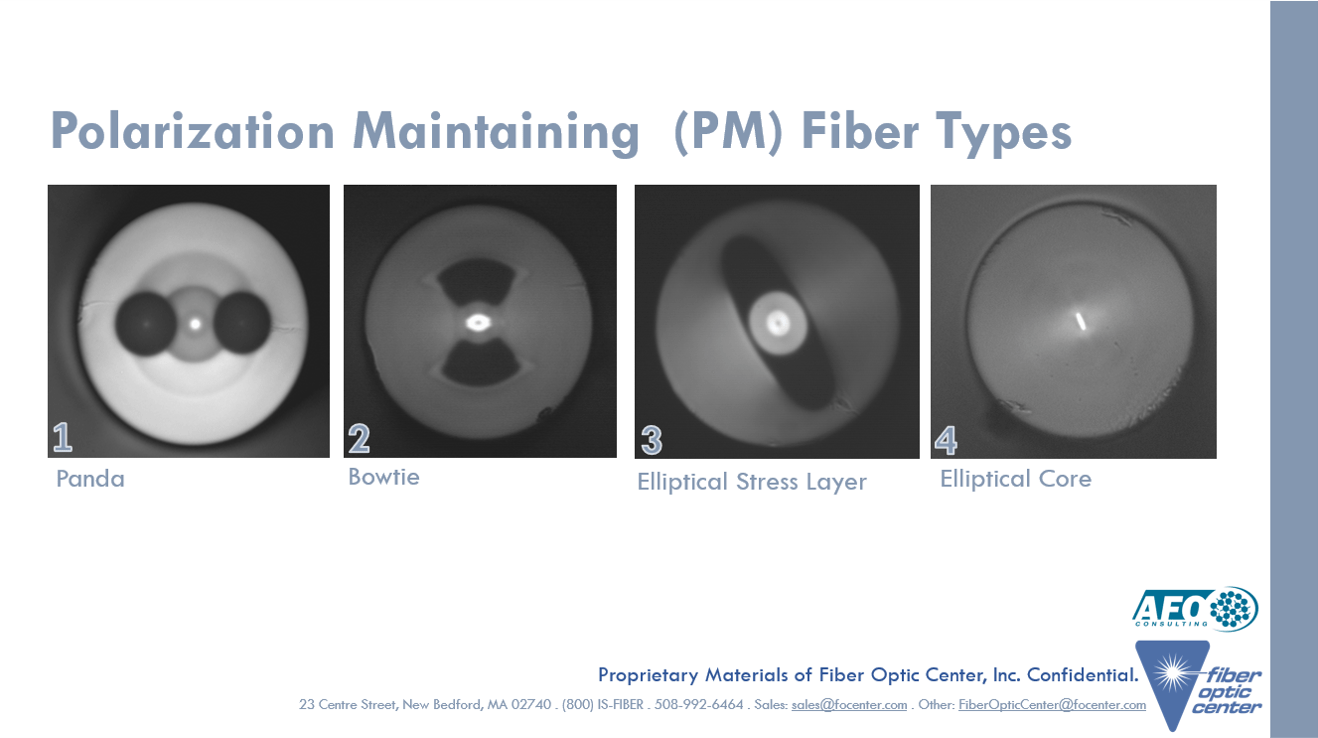
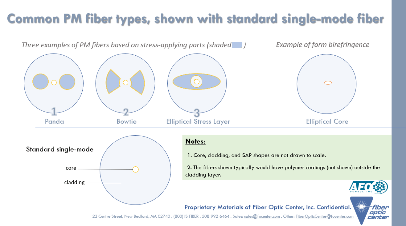
Three commercial PM fiber types that incorporate SAPs are: 1.) PANDA, 2.) bow-tie, and 3.) elliptical-stress-layer fibers. A fourth type, elliptical-core fiber, is described as using form birefringence rather than SAPs. There are other ways to achieve birefringence. One example is the use of longitudinal air holes or voids in photonic crystal fibers. The PANDA and bow-tie types are the most widely used, being preferred by many manufacturers of gyros, other sensors, and telecom components.

There are many trade-offs among the three SAP types, including the following:
- the level of birefringence that can be attained, which partially depends on the proximity of the SAPs to the core, as well as other factors;
- the size of the stress regions and the extent of asymmetry needed to achieve high birefringence, which can affect manufacturing complexity and strength;
- the ability to fabricate the stress regions uniformly throughout the fiber;
- the preform size and fiber length – bow-tie and elliptical-stress-layer PM fibers rely on the MCVD process, but PANDA can use an outside-deposition process such as OVD or VAD;
- the fiber’s strength, crack resistance, and other mechanical properties;
- the complexity of processing the preform, especially with SAPs close to the core, and preserving the SAP shapes during the draw process.
PANDA fiber has two longitudinal boron-doped glass cylinders positioned in the cladding on opposite sides of the core. Compared with the core and cladding glass compositions, the boro-silicate glass has a lower index of refraction and a higher CTE, which causes the stress regions after drawing and cooling. Fabrication relies on drilling two holes lengthwise in the preform, inserting boron-doped rods, and drawing the preform to achieve the parallel and uniformly spaced borosilicate cylinders on either side of the core. This sounds like a small number of steps, but it is an oversimplification. In practice, there are many complex procedures including:
- getting holes positioned and sized exactly right, with no cracks, imperfections, or impurities,
- obtaining or making accurately doped, uniform boro-silicate rods that fit perfectly in the holes,
- processing the preform ends to manage the induced stresses;
- keeping the SAPs round during the draw process, and many other detailed steps.
Bow-tie fiber also uses boron dopants in two longitudinal SAPs. And like PANDA fiber, the SAPs are fabricated in the cladding on either side of the core. A major difference from PANDA fibers is that the bow-tie SAPs are wedge-shaped or trapezoidal. Another difference is that they are fabricated while the preform is on the MCVD lathe. Rather than drilling and inserting rods in the cladding, the bow-tie SAPs are fabricated by depositing a layer of boron-doped glass in the cladding near the core, then selectively etching away part of that layer in two areas opposite the core, and then depositing glass with other dopants to re-fill those areas.
With this approach, the SAP can be deposited closer to the core, allowing for higher birefringence with less stress. But like the PANDA process, there are many high-precision steps and "tricks" to making the SAPs. Basically, the complexities of drilling and inserting the boron rods are replaced with the complexities of etching and re-doping, including:
- controlling the flow of etchant (usually a fluorine compound) in coordination with the size and position of the etching burners;
- etching the two regions with accurate volume and positioning and uniformity along the preform’s length;
- managing the deposition burner position and flow of dopants through multiple steps to deposit the correct core and cladding glasses in the etched areas;
- controlling the collapse of the MCVD preform to achieve the correct bow-tie SAP shape and position;
- correctly processing the ends of the preform to avoid problems with the stress regions;
The bow-tie process allows for variation in the size, position, and shape of the stress region. This gives the PM fiber manufacturer the ability to tailor the level of birefringence for different applications while balancing optical and mechanical properties. With the preform size being limited by the MCVD deposition tube diameter, the bow-tie process does not offer flexibility in the amount of fiber that can be drawn from one preform.
Elliptical-stress-layer fiber preforms are made on MCVD lathes, like bow-tie preforms. And the elliptical-stress-layer PM fiber also incorporates a ring of boron-doped glass in the cladding near the core. But, the elliptical-stress-layer fiber relies on a machining process to remove part of the cladding layer, rather than the chemical etching in the bow-tie process. In this step, the round or circularly symmetric preform is machined to have two flat sides opposite the core from each other.
This flat-sided preform (roughly rectangular in shape) is then drawn with careful control of the temperature and draw tension so that the resulting fiber is round. That is, the flat surfaces disappear or become round when the preform is heated and drawn. At the same time, the borosilicate layer (previously ring-shaped) becomes elliptical, forming an asymmetric stress region in the cladding. If the fiber is drawn carefully, the core can retain its round shape. The complexities in this method include:
- careful preform deposition and machining to avoid stress mismatches;
- accurately machining the flat sides with uniformity along the preform’s length;
- preparing the machined preform for drawing to minimize surface defects;
- controlling the draw temperature to get the correct viscosity and fiber shape;
Elliptical core fiber also uses an MCVD preform, but there are no boron-doped stress regions. Rather, the core glass is deposited with asymmetry, so that when drawn the fiber is round but the core is elliptical. To deposit the core in this fashion, the lathe rotation is stopped. The core glass is deposited on one side of the tube. When the preform is collapsed with an internal vacuum, the cladding’s outer edge stays round but the core glass becomes asymmetric. The result is a PM fiber with lower birefringence than the SAP fibers, but also with less internal mechanical stresses.
Other PM fiber types include polarizing fiber, which propagates only one mode, circularly polarizing fiber, which creates a polarization mode that rotates as it goes down the fiber, rare-earth doped PM fiber, and PM fibers with special coatings. These types have their own manufacturing complexities, such as spinning the fiber during draw, handling the CTEs and resulting stress issues of different dopants, and working with coating materials with different mechanical properties.

Applications and commercial requirements
Many specialty fibers are used in very short lengths – say meters or tens of meters – for sensing, gain media, Bragg gratings, etc. PM fibers, on the other hand, often are used in applications that can require a kilometer or more, usually wound in tight coils for gyroscopes, accelerometers, and hydrophones. Shorter lengths of PM fibers also are used in telecom pigtails, optical-coherence-tomography systems, hydrophones, fiber lasers, and other sensor applications.
The PM fiber used in gyros and other interferometric sensors usually is "bare" – that is the fiber is coated but not in a cable with strength members and an outer jacket. In many cases, the coated fiber is coiled in unit that can be less 20 mm in diameter. Further, many of these PM fiber applications are in defense and high-reliability applications that have critical strength and lifetime specifications. For example, some interferometric sensors with PM fiber are used in deep-water (high-pressure) subsea applications.
Some gyro coils can require PM fiber in lengths of hundreds of meters or up to multiple kilometers. In gyro applications, the fiber must be fabricated so that these lengths are available with no splices. For telecom components and other pigtailed applications, some PM fibers are furnished with connectorized ends, using some marking or keying for axial position. Other PM fiber applications may use splicing, and specialized fusion-splicing equipment is available from several companies.
Getting it right from preform through draw
Since the 1980s, PM fibers have come down in price by at least an order of magnitude as production quantities have gone up. Despite this, PM fibers are still significantly more expensive than communication fibers due to the complexity in production, the limitations in preform size, the quantities ordered, and yield factors. One complication in production, for example, is that you must finish the preform and draw it before you can measure the key parameters of beat length and H-parameter.
This means that you must follow the recipe carefully through every step, from burner and gas flow settings during deposition through to drawing, coating, and winding. Further, the detailed recipes for PM fibers vary from one MCVD machine to another, as well as from one type of PM fiber to another. The calibration of flow controllers and other machine settings is critical in setting and following these recipes. As with other families of specialty fibers, the ability to achieve high yields and good performance specifications when making PM fiber can depend on the experience of the engineers and technicians. FOC’s consulting team is available to review questions about PM fiber design, production, and applications.

This article is an original publication of Fiber Optic Center, Inc. It is shared publicly for educational and reference purposes to support learning and professional development within the fiber optics industry.
You are welcome to read, cite, or reference this material for non-commercial and educational purposes, as long as full credit is given to Fiber Optic Center, Inc. and the author.
Reuse, reproduction, or adaptation of this content — including rewriting, republishing, or incorporating it into new materials (such as websites, blogs, marketing text, technical guides, or AI-generated content) — is not permitted without prior written consent from Fiber Optic Center, Inc.
This material is protected by copyright law upon publication, even if not formally registered.
Use of this content for AI training, automated data extraction, or derivative content generation is prohibited.
Fiber Optic Center monitors and enforces the integrity of its intellectual property through digital identifiers and content tracking.
For more details, please refer to the Fiber Optic Center Content Use and Copyright policy.


