Myriad of Fiberoptic Polishing Variables, Process, Applications and Equipment Options
A common question in fiber optic polishing is “Can you share one standard polishing procedure”? In a perfect world, there would be ONE polishing procedure and a standard “recipe” to implement your fiber optic polishing process. Unfortunately, due to numerous factors influencing the polishing process, it’s impossible to offer a step-by-step “instruction sheet” that could accommodate everyone.
Polishing fiberoptic connectors is intuitive in principle, but in practice, there are many variables to consider when trying to determine which process and equipment are most suitable. Not all connectors and applications require the same polished end-face surface quality and shape.
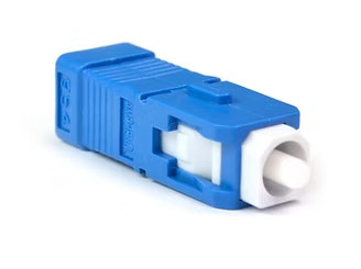
Singlefiber Ceramic Ferrule connectors
Singlefiber Ceramic Ferrule connectors are mostly used in Telecom applications. These include many connector styles, including the well-known SC, LC, ST, FC, the less common SN, E2000, MU, D4, LEMO, as well as military-style “pin-and-socket” connectors, and others.
These typically must meet industry standards for polished endface surface Visual Appearance (scratches and other defects), such as the widely accepted IEC standard 61300-3-35: “Visual Inspection of Fiber Optic Connectors”. This inspection requires the use of a microscope, typically 200 to 400x magnification.
Singlefiber ferrules must be polished with a particular convex, radiused surface geometry, with the fiber end-face polished flush with the ferrule surface, to ensure optimum fiber-to-fiber contact when two connectors are mated together. The geometries required are defined in several commonly used industry standards for end-face geometries, such as found in Telcordia GR-326, “Generic Requirements for Singlemode Optical Connectors and Jumper Assemblies” (despite the name of the document, the geometries defined in GR-326 are commonly applied to Multimode connectors as well as Singlemode). A single-fiber Interferometer is needed to measure the geometry of a polished end-face.
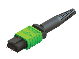
Multifiber Plastic Rectangular Ferrule connectors
Multifiber Plastic Rectangular Ferrule connectors, namely the MTP/MPO connector, which is often referred to as simply “MT” ferrule connectors, are also widely used in Telecom and Data Center applications.
These types of connectors also must meet Visual Appearance standards such as IEC 61300-3-35, and thus also require a microscope to visually evaluate each fiber for scratches and visual defects.
MT ferrules must be polished with different surface geometries than single-fiber connectors. Because the ferrule holds multiple fibers, it must be polished with a “flat” (not radiused) end-face, with all fiber end-faces protruding a certain distance above the ferrule surface, to ensure good fiber-to-fiber contact when two connectors are mated. Multifiber ferrule end-face geometries are defined in such industry standards as USConec’s AEN-1915, “USConec Recommended MT Ferrule Endface Geometry”. A multifiber Interferometer is needed to measure the geometry of polished MT ferrule end-face.
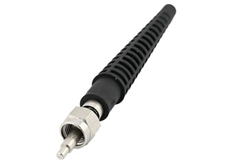
Metal-body Ferrule or SMA connector
Metal-body Ferrules, primarily the SMA connector, are commonly used in medical and high-power laser applications, using large-core MM fibers.
Because of the wide range of applications and fiber sizes used in SMA’s, the Visual Inspection requirements are often case-by-case and not “industry standardized” as are the Telecom style connectors. However, a microscope is needed to visually inspect the polished end-face. In high-power laser applications, the end-face Visual requirements can often be more strict than those used in Telecom style connectors.
SMA connector endfaces are typically polished “flat” with no specific “industry standard” endface geometry requirements. The SMA connector is not designed to have fiber-to-fiber contact when two connectors are mated. Instead, there is a designed air-gap between the two mated end-faces and because of this, polished SMA ferrules often must conform to the requirements of IEC 61754-22 for ferrule length. Ferrule length must be measured with a specialized Ferrule Length Gauge to ensure that the finished ferrules are neither too long or too short, which would result in an air-gap between mated ferrules is either too small or too large.
Universal Polishing Procedures
In a perfect world, there would be ONE polishing procedure for all to follow, as a standard “recipe”, for streamlined implementation. Unfortunately, due to numerous factors influencing the polishing process, it’s impossible to offer one step-by-step “instruction sheet” that accommodates all needs. Ideal fiber heights are often determined by inconsistent direction from IEC’s international standards to industry and manufacturer specifications creating a need for full evaluation and custom recommendations.
The good news is, there are some standard practices to follow and Fiber Optic Center offers consulting on the general guidelines for How to Develop a Fiber Optic Polishing Process that Produces Consistent Results.
It is standard to clean between each polishing step and to meet certain geometry and visual appearance requirements. While there may not be one polishing procedure specifically, there are a few basic ingredients to every recipe: time, pressure, and speed. In all cases, the goals for polishing are similar:
- Create a clean fiber end-face, free of surface defects (scratches/cracks) that will limit light transmission/coupling.
- Create an end-face geometry sufficient for the light transmission requirements.
- Do so in a repeatable/reproduceable/efficient manner.
To properly meet these goals, we need do essentially 3 things:
- Hold the ferrule at precise angle during polishing (fixturing, or “puck”)
- Apply consistent downward pressure on the ferrule during polishing
- Polish using a series of descending grits of lapping film
The exact recipe for your polishing procedure depends on certain factors in your fiber optic cable assembly process: equipment, methods, polishing film materials, and environment married with the specific objectives and goals in the polishing process and required specifications. The following paragraphs address some of the variables that affect the polishing process – and help to shed light on why a one-size-fits-all, universal polishing process does not exist.
Equipment: Machine vs Manual Polishing
Generally speaking, when it comes to polishing machines, there are some commonalities. For example, every polishing machine needs to apply pressure to the ferrule for a certain amount of time. The polishing medium needs to be in motion to abrade the surface (to polish away material). All polishing machines work in a series of steps, starting with a rough grit of polishing film and moving to a finer grit.
The specific polishing machine you use will significantly impact the process because various manufacturers employ different philosophies regarding how they approach polishing. Machines utilize different methods to apply pressure, different patterns of motion to use the complete area of the film, and different lengths of time:
- Pressure – Methods to apply pressure include pneumatic pistons, mechanical clamps, pulling, and pushing.
- The different motions of the abrasion film – Some polishing machines use a circular motion, some use a figure-8 motion, and most use a two-axis spinning-and-rotation motion (essentially, a continuous spiral moving over the surface).
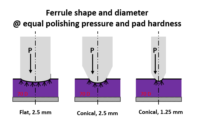
The type of polishing machine – as well as the condition of equipment and accessories – are key factors.
Manual: All connectors can be polished successfully using a manual polishing process. However, because the ferrule is held and pressure is applied by hand, manual polishing is inherently less repeatable in creating a targeted surface finish. Also, since manual polishing is done on individual connectors one at a time, throughput is low and labor content is high. Manual polishing is usually best reserved for emergency repairs, when machine polishing is not able to be done, or in situations where the quality of the polished end-face is not critical.
Machine: Machine polishing allows for very repeatable end-face surface finish because ferrules are held securely, pressure is applied extremely consistently, and many connectors can be polished at one time. Machine connector fixtures commonly hold from 12 to 24 single-fiber connectors, some even going as high as 72 connectors, as thus results in greatly higher output than manual polishing. For efficient and consistent polishing results, machine polishing is always preferred.
The most common bench-top polishing machines, made by Domaille Engineering or Seikoh Giken, are relatively heavy and bulky and often require compressed air connection in addition to electricity to operate. This makes them not easily portable. In contrast, there are smaller capacity model polishing machine that, though not as efficient and repeatable, are more easily portable, only requiring electrical or battery connection. These are suitable for field polishing.
Fiber Optic Center’s equipment selection process, contamination control, lapping film considerations and increasing bandwidth of data transmission needs are all discussed in the FOC article, Polishers: Discussion on Expense and Top Technology.
Polishing Process
When developing a machine polishing process, the first step is familiarization of the product end-face objectives:
- What are the end-face Visual requirements, if any (i.e. IEC 61300-3-35)?
- What are my Geometry requirements, if any (i.e. Telcordia GR-326 or USConec AEN-1915)?
- What are my ferrule length requirements, if any (i.e. IEC 61754-22)?
While there is no “one” polishing process that works for all connector types and end-face requirements, all polishing processes do share some common practices:
- There are multiple polishing steps (typically 3 or 4 steps), starting with a “rough” grit lapping film and descending to a final “fine” grip step.
- Films are placed on either rubber pad (to generate the Radiused endface required for most single-fiber ceramic ferrule connectors) or on glass pad (to generate the flat endface for required for most MT and SMA connectors)
- Water is used on the films during polish, for lubrication and for helping keep the lapping film from getting “clogged” and reducing the cutting effectiveness.
- The fixture and ferrule end-faces must be thoroughly cleaned between each polishing step, to remove contaminants generated during the preceding polishing step.
- Polishing machines allow process control of 3 main variables in each polishing step: The Pressure applied, the Speed of the machine platen, and the Time for each step. While the “optimum” setting for Pressure, Speed and Time often will vary depending on connector type and manufacturer, a good starting point for machine settings can be found here:
-
- Domaille: POLISHING INSTRUCTIONS FOR DOMAILLE 4 AND 5 SERIES
- Seikoh Giken: POLISHING INSTRUCTIONS FOR SEIKOH GIKEN SFP-560
-
Singlefiber Ceramic Ferrule polishing
Singlefiber Ceramic Ferrule polishing must have lapping films placed on the rubber pad backing to generate a radiused ferrule endface. Typically this is a 4-step process for 2.5mm ferrules (such as SC, FC, ST, etc.). However, a 3-step process may be used for smaller 1.25mm ferrules (such as LC, SN, MU, etc.)
Singlefiber Ceramic Ferrule Polishing Steps:
Step 1, Epoxy Removal: Goal is to remove the epoxy bead remaining on the ferrule endface from the Termination process. This step is a rough grind, typically done with a 16um (or higher) Silicon Carbide film.
- For angled (or “APC”) polishes, this step will serve to cut the angle across the ferrule endface which also serves to remove the epoxy bead.
Step 2 and 3 (if used), Shaping: Goal is to shape the proper radius along the ferrule endface while removing the defects/scratches generated by the preceding polishing step. This is best achieved using diamond lapping films, due to their ability to cut through the ceramic of the ferrule and their durability (diamond films can often be used 10x or more). Usually, the last Shaping Step uses a 1um diamond lapping film.
Step 4, Final Polish: Goal is to remove all fine scratches remaining from the preceding diamond polishing step, and to generate the required Fiber Height geometry requirement. This is typically achieved using a sub-micron-sized Silicon Dioxide lapping film.
- Angled, or “APC” Polishing is essentially the same process as non-angled, or “PC” Polishing, the only difference being that the APC polishing fixtures hold the connectors at the desired angle during polishing.
More tips and recommended polishing practices can be found at the following links:
- Polishing Tips and Best Practices for Single Fiber Connectors
- APC Polishing Advice to Improve Apex Offset and Angle Measurements
- Steps to Overcome Common APC Polishing Issues
- Polished Connector Geometries, APC
- How to Develop a Fiber Optic Polishing Process that Produces Consistent Results
- Polishing FAQS: What to Do (And What Not to Do) In Your Fiber Optic Cable Assembly Polishing Process
MT Polishing
MT Polishing must have lapping films placed on a glass pad, to polish the ferrule endface “flat”. MT polishing requires very precise polishing to achieve demanding geometries above and beyond Singlefiber ferrule requirements (for example: MT Ferrule Geometry Specifications: Minus-Side Coplanarity in IEC 61755-3-31:2015.
Cleaning is more difficult for MT’s than it is for singlefiber connectors because of the guide-pin holes in the MT ferrules. These holes will get filled with contaminants during each polishing step, and it is critical that these holes are cleaned out properly between steps. MT ferrules are typically polished using a 4-step process.
MT Ferrule Polishing Steps:
Step 1, Epoxy Removal: As with Singlefiber polishing, the goal of Step 1 is to remove the epoxy bead remaining on the ferrule endface from the termination process. This step is a rough grind, typically done with a 16um (or higher) Silicon Carbide film.
- For angled (or “APC”) polishes, this step will serve to cut the angle across the ferrule endface which also serves to remove the epoxy bead.
Step 2, Fiber Height generation: This step is typically performed using a specialized 3um Silicon Carbide film, designed specifically for MT polishing. This step removes more plastic ferrule material than fiber, and generates the majority of the required fiber protrusion from the surface of the MT ferrule (as required by MT Geometry standards). Using the Chemical Mechanical Planarization (CMP) process to polish MT Ferrules uses a flock pile pad to provide a hybrid of chemical etching and abrasive polishing.
Step 3, Medium Polish: Goal is to remove the defects from the preceding step, while maintaining as much of the generated fiber height as possible. This is done with a “flocked” film (a cloth-like film) of 1um Aluminum Oxide.
Step 4, Final Polish: Similar to Step 3, but using a finer Flocked film with sub-micron Silicon Dioxide abrasive.
SMA Polishing
SMA polishing processes will vary greatly depending on the fiber size and SMA type, but typically are similar to Singlefiber polishing steps. However, since the SMA ferrule is steel and not ceramic, Aluminum Oxide lapping films are often preferred instead of the more aggressive diamond films.
Many, but not all, SMA applications require that the ferrule length, after polish, is within certain limits. In those situations, the process must be closely controlled to ensure that too much ferrule material is not being removed during the polishing process. SMA critical length and guides are provided in the blog How Can I Tell I Have Over-Polished a Connector?
Polishing Films
Polishing films are available in many different configurations:
- Grit sizes: from sub-micron to 30um or higher.
- Abrasive Material:
- Diamond Lapping Film: reuseable, high durability and consistent cut rates through ceramic and glass; expensive. Ideal for ceramic ferrule shaping. Diamond films can typically be used 10-20x or more.
- Silicon Carbide Lapping Film: effective for rough grinding, such as the Epoxy Removal stage of polishing, typically 1-5x use.
- Aluminum Oxide Lapping Film: typically a 1x use, AO films are a good polisher for glass, but not very effective with cutting ceramic ferrules. Aluminum Oxide films are usually used with SMA polishing.
- Silicon Dioxide: typically can be used 3-5x in sub-micron sizes as a “final” polishing film. Silicon Dioxide final films are excellent at producing a defect-free endface, while maintaining required Fiber Height geometries.
- Film sizes:
- 5” Disks (for most commercial polishing machines).
- 8.5 x 11 sheets for manual polishing.
- Custom smaller disks, roll format, etc.
- Film Backing
- Adhesive-backed (PSA-backed) films allow for secure placement of the film on the rubber or glass pad, ensuring that the film will not “slip” during polishing.
- Non-adhesive-backed (non-PSA-backed) films are more difficult to secure to the rubber or glass pad, but desirable when “flatness” is critical (the adhesive layer of PSA-backed films can act as a cushion and create a slightly radiuses end-face, even when polishing on a glass pad for flatness).
- Film Type:
- Most typical films are mylar-backing with the abrasive film “painted” on one side. This type of film is used for singlefiber ceramic ferrule polishing, as well as SMA.
- “Flocked” films, used in MT polishing, are not really “films” at all, but cloth-like material with the abrasive material embedded in the cloth. Flocked films are essential for achieving MT ferrule geometries.
Slurries
While not “films”, abrasive slurries can be used in a similar fashion to films. Slurries are a suspension of abrasive material, available in the same sizes and materials as film abrasives, that can be applied to a holding pad and used to polish just like with films. Slurries are rarely seen in connector polishing these days: slurries can be much cheaper material cost than films, but they are more messy and difficult to clean requiring more process controls than films. Slurries are generally not preferred for typical connector polishing except in special situations.
For more information on lapping films, view the Fiber Optic Center Lapping Film Technical Library for a comprehensive database of resources, including technical papers, articles, an Overview of Lapping Film, best practices, tips, FAQs, and more.
Polishing Pads
Films must be placed on a Polishing Pad during polishing. Polishing pads are either rubber or glass, depending on if you need to generate a radiused endface or a flat endface. Pad shapes and sizes will depend on the platen size of your polishing machine, but 5” diameter pads are most commonly used on polishing machines.
Rubber Pads
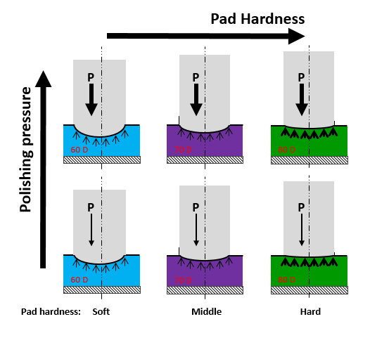
Rubber pads are required for generating the Radius of singlefiber ceramic ferrules. The magnitude of the radius generated is determined by the hardness of the rubber pad: Harder pads will produce a larger (flatter) endface radius, while softer pads will produce smaller (more rounded) end-face.
Because of the variation in singlefiber ceramic ferrule diameters, shapes, and ceramic composition, different pad durometers for different ferrule types may need to be used. Typically, smaller diameter ferrules (such as the 1.25mm LC) will normally use an 80D or 90D rubber pad, while larger diameter ferrules (such as the 2.5mm SC) will normally use a 70D or 80D rubber pad to achieve the same radius.
The consistency of the rubber pad thickness and durometer is critical to achieving repeatable geometry results on singlefiber ceramic ferrules. It is highly recommended to only use rubber pads provided by the polishing machine manufacturer.
Glass pads
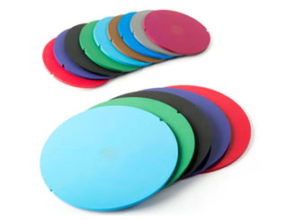
Glass pads will result in a nearly flat end-face, and are required for MT polishing, and often for SMA polishing as well. Glass pads are available as either just plain flat glass plate, or with a frosted/etched or tacky surface. If using PSA-backed films, simple plate glass will suffice. However, if using non-PSA-backed films, it can be difficult to prevent the film from sliding during polishing. The frosted / etched or tacky-surface glass pads help to mitigate the chance of film slippage during polishing.
Plates and Pads are broken into two different types: Machine Polishing Plates and Pads (specific to the Domaille Engineering or Seikoh Giken polishing machines) and Manual Polishing Plates and Pads. In fiber polishing, it is critical to prevent polishing lapping film from moving because connectors are not being polished if the film moves with the polishing machine’s platen. Helpful tips for ensuring no movement of both rubber pads and glass plates and cleaning procedures for both can be found here: Polishing FAQS: What to Do (And What Not to Do) In Your Fiber Optic Cable Assembly Polishing Process.
Polishing Fixture / Polishing “Pucks”
Connectors are held during polishing by “polishing fixtures” for machine polishing, often referred to as pucks for manual polishing.
- Fixtures typically hold multiple connectors to polish at one time.
- Manual pucks hold 1 connector at a time.
These fixtures are extremely important in determining the final endface geometry of the ferrules and are designed per connector style, and thus you must have 1 fixture for each connector type you want to polish. (for example, and LC fixture can only polish LC connectors, an MT fixture only MT connectors, etc.).
Fixtures have precision-machined ferrule bores, which are essential for maintaining consistent endface geometries. Over time of repeated insertion and removal of connectors to the fixture, the hole bore (or any latching features in the plate to hold the connector during polishing) will gradually wear out and need replacement. Machine polishing fixtures will wear with use, but generally should be expected to last ~5 years in moderate-volume manufacturing before needing replacement. Manual polishing “pucks” will wear much faster, and need more frequent replacement.
Cleaning
In-process Cleaning of the films and ferrules between polishing steps is critical to attaining defect-free endfaces. Maintenance cleaning of the polishing fixture and machine after use is critical to maintain performance and resulting endface geometries.
Cleaning between steps
The bottom of the fixture, and the ferrules protruding from it, need to be thoroughly cleaned between polishing steps, to ensure all the contamination generated during the preceding polishing step is rinsed away before proceeding to the next polishing step.
Such cleaning can be done in many ways effectively, but it is always preferable to reduce rubbing the fiber endface with a material which may cause scratches during the cleaning. Spraying with water, and then agitating by rubbing with a lab-wipe or soft brush may be acceptable, but does introduce a risk of scratching. More “non-contact” cleaning methods are preferred.
- Pressurized water spray systems, such as the Domaille Air Cleanse system, are an excellent way to clean between steps, as there’s no contact with a lap wipe or brush that may cause scratches on the fiber endface.
- Ultrasonic cleaning can be very effective, but requires moving the fixture (and the connectors/cables mounted to it), and may not be reasonable.
Cleaning of fixtures after polish
Polishing fixtures should be thoroughly cleaned and dried once they are through being used for the day. This is best done by using an ultrasonic cleaner, then blowing dry with compressed air. Proper cleaning of the fixtures will extend the life of the fixture and quality of the polishing results. There are eight best practice steps to clean and maintain polishing fixtures for proper optical fiber polishing machine maintenance.
Because contamination of the fixture is so critical to precision, the four major effects to consider have been detailed in the article, Fiber Optic Polishing Fixture Maintenance: Fiber Optic Polishing Fixture Contamination and Ultrasonic Cleaning.
METHODS
Product specification requirements dictate the polishing methods. Determining the requirements is critical. Many companies invest in consultation with the Fiber Optic Center Technical Team to identify these and develop methods and process from that discovery. Examples include:
- Applications requirements range from PC finish, flat finish, angled PC, and angled flat.
- Specifications can range from both allowing and NOT allowing scratches on the fiber’s core as well as requiring a very rough surface or a non-rough surface.
- There are different end face finish requirements that define how rough the surface can be.
Most fiber optic cable assemblies have very specific geometry requirements but there are some requirements that are wide open. All these factors, taken together, will dictate the polishing methods needed to achieve your end goal and meet the requirements.
ENVIRONMENT
Temperature and cleanliness are often overlooked environmental factors that impact the polishing process.
If your polishing process uses rubber pads, it’s helpful to remember that pads age over time by UV exposure. Plus, they are sensitive to temperature changes. Ambient temperature will change the hardness of the rubber pads and, thus, change the results of your process. The aging process of rubber pads is not homogeneous and starts with hard spots in the rubber. As a result, the average ferrule Radius values remain acceptable, but the Apex values decline.
Cleanliness, as discussed above, impacts the polishing process. Because all polishing processes are multistep, between steps, it is critical to clean the polishing material away from the ferrules as you transition from a rougher-grit to a finer-grit polishing film. Plus, think about your environment. The polishing process creates contamination as you grind material from the ferrule. The level of cleanliness in your polishing environment will impact the amount of cleaning needed on the product and films between every step.
IN CONCLUSION
The above discussion is not meant to overly confuse or intimidate those looking to enter the fiber optic ferrule polishing world, but to explain the variables at play that will affect any polishing process. This explanation of why a one-size-fits-all, universal polishing process does not exist is important for those considering entering the polishing world.
When implementing a polishing procedure, request a Fiber Optic Center consultation that will include all the factors noted in this article. A Polishing Instruction on recommended polishing machine settings are meant to serve as a general reference for a good starting point for your polishing process development. It is expected that minor changes to some recommended machine parameters will be needed in order to meet your specific product needs. In addition to the machine specific instructions, custom best practices are provided. Fiber Optic Center partners with the customer to make sure their manufacturing procedures produce the highest quality jumpers at the most effective cost basis.
The FOC Technical Team consultation services include but are not limited to:
- On-site polishing process development (tighter control on geometry, reducing film cost and increase capacity).
- Best practice and proper selection of consumables: polishing film and epoxy.
- Preventive maintenance, equipment calibration and verification.
- On-site repair, loaner equipment to ensure production continuation.
- Final inspection on produced cable assemblies (containing overall appearance, connector geometrical, optical and visual inspection connector as well as cross-sectioning.)
We invite you to explore the Fiber Optic Center Technical Content Library for answers to your most pressing fiber polishing questions. Search a comprehensive database of resources, including technical papers, best practices, tips, FAQs, and more. Timeless top topics include:
- Polishing Technical Solution Content
- Glossary, Acronyms, Military Specifications for Connectors
- Polishing Tips and Best Practices for Single Fiber Connectors
- Fiber optic polishing FAQs, general tips and news
- Q&A Resource: email technical questions to AskFOC@focenter.com
Our world is about helping YOU select the right equipment and materials while providing expert knowledge for best practice processes. Fiber Optic Center is the partner for ensuring long-term product reliability.
This article is an original publication of Fiber Optic Center, Inc. It is shared publicly for educational and reference purposes to support learning and professional development within the fiber optics industry.
You are welcome to read, cite, or reference this material for non-commercial and educational purposes, as long as full credit is given to Fiber Optic Center, Inc. and the author.
Reuse, reproduction, or adaptation of this content — including rewriting, republishing, or incorporating it into new materials (such as websites, blogs, marketing text, technical guides, or AI-generated content) — is not permitted without prior written consent from Fiber Optic Center, Inc.
This material is protected by copyright law upon publication, even if not formally registered.
Use of this content for AI training, automated data extraction, or derivative content generation is prohibited.
Fiber Optic Center monitors and enforces the integrity of its intellectual property through digital identifiers and content tracking.
For more details, please refer to the Fiber Optic Center Content Use and Copyright policy.


