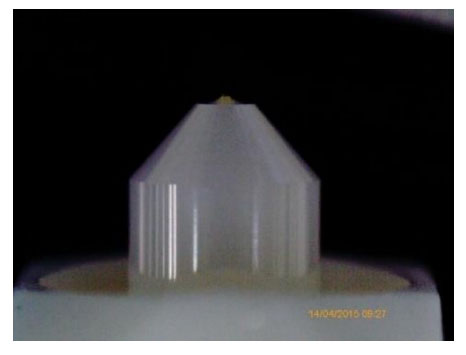
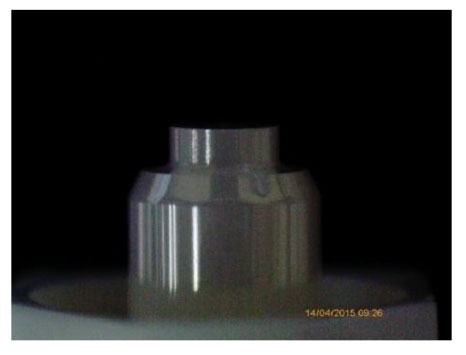
Of the two common ferrule shapes involved in APC polishing – conical and step – the step ferrule is by far the easiest in terms of controlling geometries. Step ferrules are more expensive than conical ferrules. However, from a purely process-control point of view, step ferrules are absolutely the easiest and best choice. If you are new to APC polishing, it is highly recommended to use step ferrules over conical. Step ferrules are less sensitive to minor process and material variations, and they are much easier to work with when it comes to developing and modifying polishing processes. Thus, using step ferrules results in significantly improved first-pass yields.
To ensure optimum performance between mated pairs of APC connectors, it is important that the ferrule endface geometries meet or exceed industry-accepted endface geometry standards1. The most common issues that polishing process engineers face regarding APC polishing geometry usually involve the Apex Offset and Angle measurements. There’s quite a bit of complex trigonometry to mathematically “prove” the geometrical consequences involved in forming and measuring a curved angle across a conical or cylindrical object (the ferrule). But it’s not necessary to delve too deeply into complex math. Simplified diagrams are sufficient to help polishing process engineers visualize the basic principles at work, enabling them to better control their polishing process to meet the product’s geometry needs.
To understand APC polishing, it is helpful to start by reviewing PC polishing. The mechanisms at work affecting Apex Offset and Angle are the same, but it is simpler and more intuitive when describing PC polishing.
Apex Offset and Angles in PC Polishing
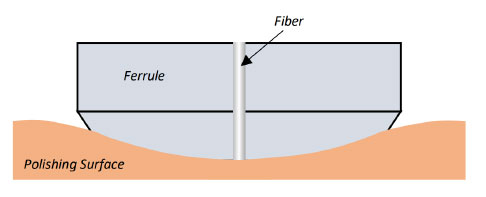
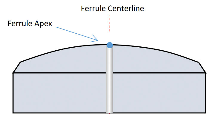
Apex Offset is a fairly simple concept to understand in PC polishing. With PC ferrules, the intention is to hold the ferrule at a 0.0 degrees vertical angle during polishing (perpendicular to the polishing surface). As long as the ferrule is perfectly perpendicular to the polishing surface, the Apex (highest point) of the radiused endface will be the exact center of the ferrule, and Apex Offset value will be zero2 (Figures 1a and 1b).
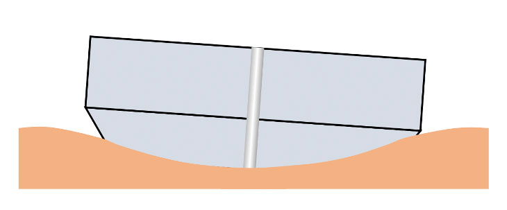
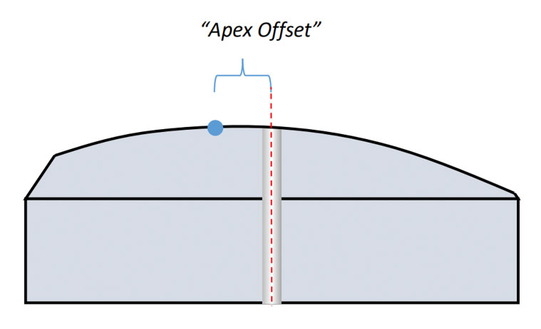
If the ferrule is not perpendicular to the polishing surface, the Apex of the curved endface will not be centered on the ferrule: an Apex Offset value > 0 (Figures 2a and 2b).
The more the ferrule is angled away from perpendicular, the farther away the Apex of the Radius will be from the ferrule’s center – thus the larger the Apex Offset value will be. Apex Offset is directly proportional to the angle with which the ferrule was polished. In fact, Apex Offset and Angular Offset are two ways to express the same thing, they just use different units of measurement. (Apex Offset is measured in microns from the fiber center, whereas Angular Offset is measured in degrees from the fiber center axis.) Since Angular Offset is a common cause of Apex Offset measurement issues, polishing process engineers can identify the following as a general Geometry Process Rule:
- All other factors being equal, the bigger the difference between the intended polishing angle and the actual polishing angle, the bigger the measured Apex Offset (or Angular Offset) value will be.
Furthermore, since the endface is polished with a radiused (domed) surface, we know that the surface angle of any two points along the curve will not be equal.That is, the Angle at my Apex point and the Angle at my ferrule centerline point can never be equal (Figure 3). (We’re assuming the dome created is perfectly spherical, which is unlikely in reality but is not relevant to our discussion.)
Here’s another important concept to keep in mind: The tangent angle at my Apex point will always be exactly the angle at which I held the ferrule during polishing. If I held my ferrule at exactly 0.4 degrees from perpendicular during polishing, this will produce an angle at my Apex point of exactly 0.4 degrees from horizontal. This concept is important to remember when we discuss APC polishing.
Apex Offset and Angles in APC polishing
All of the above also applies when polishing APC ferrules – the only difference is that, with APCs, we are intending to hold the ferrule at an angle to the fiber/ferrule axis during polishing (typically 8 degrees) instead of perfectly vertical (0 degrees). This introduces other factors that have significant impact on Apex Offset and Angle measurement values – namely ferrule SHAPE, end-face RADIUS, and KEY ERROR.
Note that Key Error is a major component of measured Apex Offset values. Key Error is the “rotational component” of Apex Offset. For example, if the adapter keyway slot in my interferometer is significantly wider than the key width on my APC connector, you can imagine it is possible for me to rotate the connector slightly during measurement, resulting in erroneous measurement values. It is a complicated topic to fully explain and is worthy of its own article. Because of this complexity – and the fact that Key Error problems are less common than Angular problems – I will not discuss Key Error in great detail in this article.
First, let’s look at ferrule shape. There are two common types of APC ferrules in terms of shape: conical and step.
- The conical ferrule (Image 1), naturally, has a cone shape to the polishing area of the ferrule.
- The step ferrule (Image 2) has as cylindrical shape to the polishing area of the ferrule.
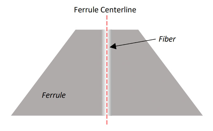
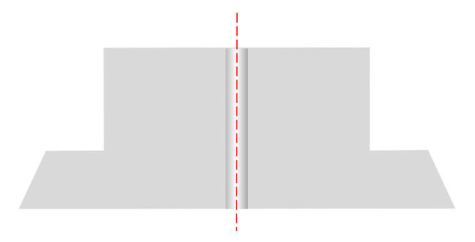
Figures 4a and 4b present cross-section diagrams of the two ferrule types. The gray areas are the ferrule material, the center is the fiber, and the red-dashed lines show the centerline of the ferrule diameter.
Now we need to consider the results of cutting an 8-degree angle through both of these shapes. We’ll start with the conical ferrule shape.
Conical shape and Apex3
If we cut a straight line through the conical ferrule, we can see that – due to the cone shape – any angle cut flat across the surface leaves us with unequal distances from the center to the outside edges of the ferrule. (For the moment, we’ll forget about any Radius on the endface; we’ll address this point later in this article.)
In Figure 5, we can see the distance from the center to the left (lower) edge is larger than the distance from the center to the right (higher) edge:
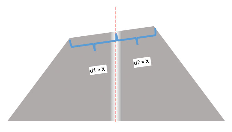
Figure 5: Cutting an angled plane though a cone: The distance from the center to the left-hand edge (d1) is larger than the distance from the center to the right- edge (d2)
If we put a straight line across the angled surface, its mid-point will not be – and can never be – in the center of the ferrule (Figure 6).
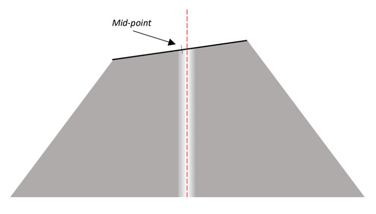
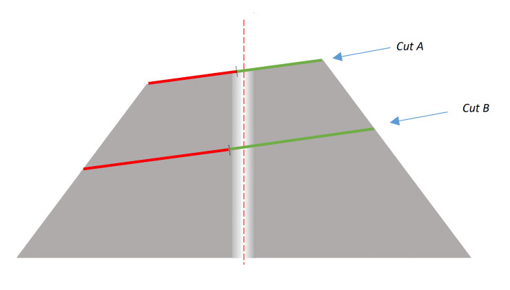
As we polish away more and more material from the cone shape, the center point moves farther and farther away from the centerline. This mid-point will NEVER be in the center of the ferrule, and will move farther and farther away from center as we remove more material – and cut the ferrule shorter and shorter (Figure 7).
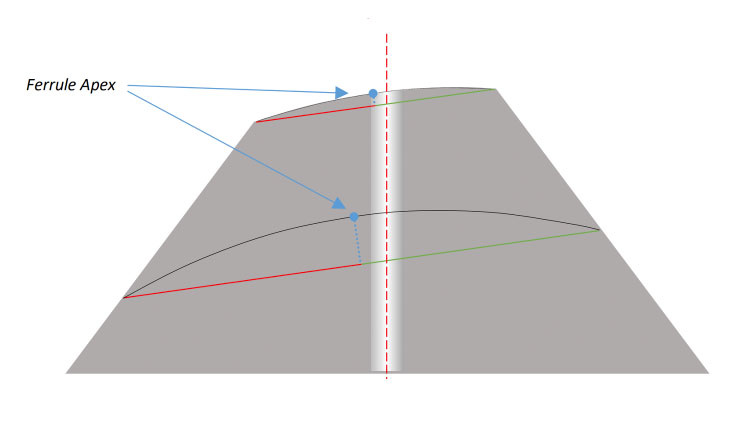
Now let’s consider what happens when that surface has a radiused face instead of being perfectly flat. In Figure 8, I have added 5mm radii to two different locations on the ferrule. As expected, the ferrule Apex will be even farther from center than the mid-point of the cut. Plus, it will continue to move farther and farther from the ferrule center as more material is removed.
Now we see that if I polish a conical ferrule at 8 degrees – then measure in an interferometer (which also holds the ferrule at 8 degrees) – it is virtually impossible for me to get good Apex Offset measurements. Therefore, here is another Geometry Process Rule:
- Conical APC ferrules MUST be polished at an angle greater than 8.0 degrees (typically either 8.2 or 8.3 degrees).
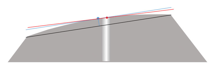
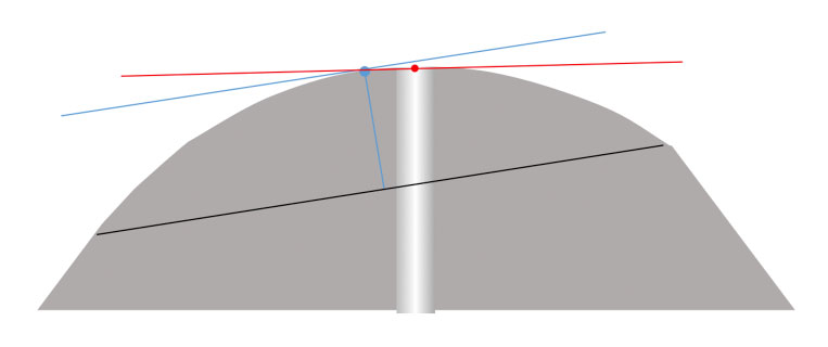
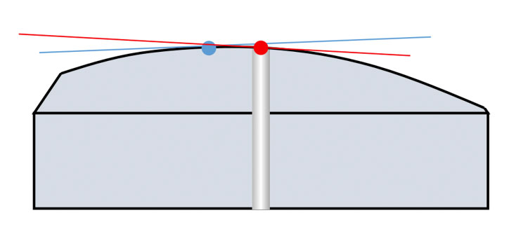
Because we always hold ferrules at exactly 8.0 degrees when measuring in an interferometer, if we polish the conical ferrules at 8.3 degrees, our measured Apex will be closer to the center of the ferrule. The shape of the ferrule remains constant – my “ferrule Apex” is still far off-center. But because we are measuring from a different relative angle, the “measured Apex” will be a different point4 (Figures 9a, 9b, 9c).
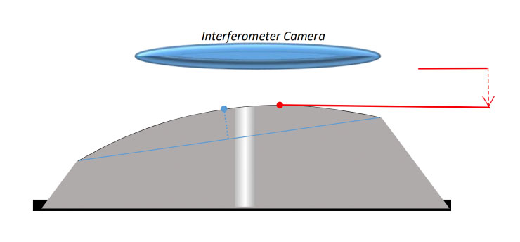
Figure 9a: This represents my ferrule after polishing at an angle of 8.3 degrees (not drawn to scale). The ferrule Apex, relative to 8.3 degrees (blue line), is the blue dot. If I insert the ferrule into the interferometer with no tilt, the “measured apex (the point closest to the interferometer camera, red lines and dot) is far off to the right, obviously well away from the center of the ferrule.
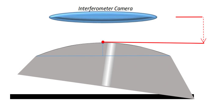
Figure 9b: If I insert the ferrule into the interferometer at an 8.3-degree tilt (again, improper), both points are now in the exact same position, as expected. My ferrule Apex is in the exact same position as my measured Apex.
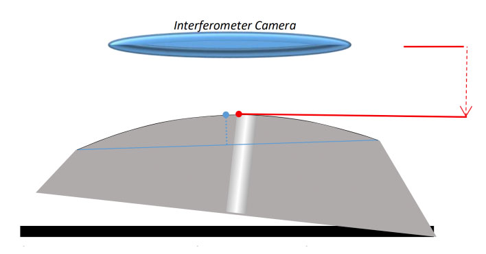
Figure 9c: If I insert my 8.3-degree polished ferrule into the interferometer at an 8.0-degree angle - the proper angle for geometry measurements - my measured Apex (red) will always be closer to the ferrule center than my ferrule Apex (blue)- and my Apex Offset value will be reduced.
By using a larger angle to polish than I use to measure, I can achieve much better Apex Offset measurements. But it still holds that, because of the conical shape, the more material I remove (the more I polish), the worse my measured Apex Offset value will be (the ferrule Apex will continue to move “to the left” or toward the lower side of the ferrule). This gives us another useful Geometry Process Rule:
- For any given Angle and Radius with conical ferrules, the more I polish, the more my Apex Offset will move to the direction of the lower side of the angled ferrule.
Conical shape and Angle
Now we need to look at the measured Angle. As we discussed earlier (see Figure 5), each point along a domed surface has a different angle to horizontal – the tangent to the Radius at that point. At the ferrule Apex, the Angle will be exactly the same as the Angle the ferrule was held at during polishing. But for our interferometer measurements, we only care about the Angle at the fiber region: the center of the ferrule. And the Angle at the ferrule center (the fiber region, where we measure Angle values) will ALWAYS be less than the Angle at which we polished (Figure 10) when the Apex is on the “low side” of the angle, and will ALWAYS be greater than the Angle at which we polished (not drawn) when the Apex is on the “high side” of the angle.
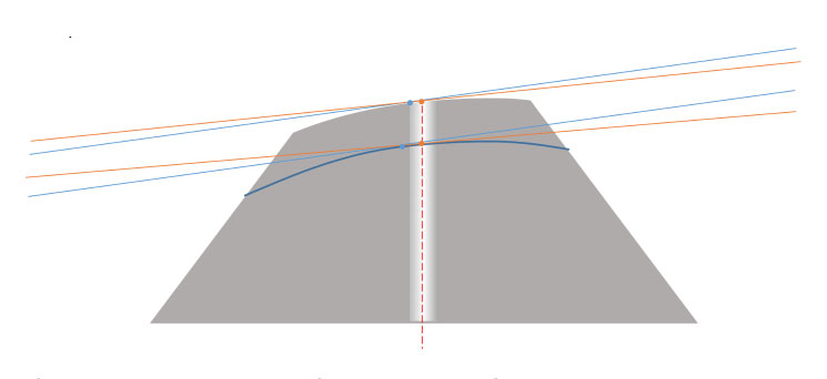
As we remove more and more material and cut farther down the conical ferrule, the Angle at our Apex stays constant, while the Angle at our centerline (the fiber area) gets smaller and smaller. And since we are only interested in measuring the Angle at the fiber region of the ferrule, we can conclude another Geometry Process Rule:
- For any given polishing Angle and Radius, the more I polish a conical ferrule, the smaller my angle in the fiber region will become.
- If my measured angle is too big, I can fix this by simply polishing more material away (more polishing time).
- If my measured angle is too small, I cannot fix this by polishing more – I’d need to modify my process to remove less material (less time, or less aggressive polishing films) and start again.
Radius effect on Angle
Now we come to the effect that our Radius value has on our Angle in the fiber region. We already know that, because the surface is spherical, the Angle at the fiber region will always be different than the Angle at the ferrule Apex (see Figure 10). But the magnitude of that difference in Angle depends on how curved the Radius is. A larger Radius (“flatter”) will have a smaller difference; a smaller Radius (“rounder”) will have a larger difference (Figures 11a and 11b).
This gives us two more Geometry Process Rules:
- Increasing my Radius will increase the Angle at my fiber region. (This applies to conical and step ferrules.)
- Increasing my Radius will decrease the Apex Offset. (This applies to conical and step ferrules.)
We can see that with conical ferrules, the depth to which we cut – how far down the ferrule we cut and how much material we remove – needs to be very well controlled if we are to have any hope of controlling our measured Apex Offset and Angle values. As we’ll see, the step ferrule does not require such focus on depth of cut.
Step shape and Apex
The effects of cutting a radiused Angle through a step ferule are much easier to explain and understand. Because of its cylindrical shape, any Angle cut flat across the surface will have exactly the same distance from the center to the outside edge (Figure 12).
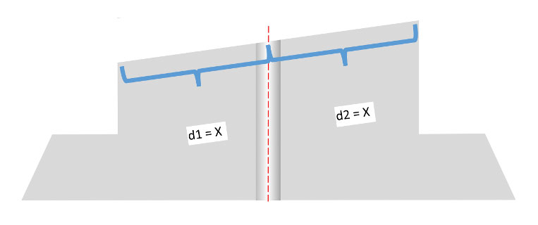
Figure 12: The midpoint of an angle cut through a cylinder will always be in the center.
Because of the constant diameter of the cylinder, the centerline of the Angle will always be in the center of the ferrule, regardless of how much material is removed in the polishing process (Figure 13).
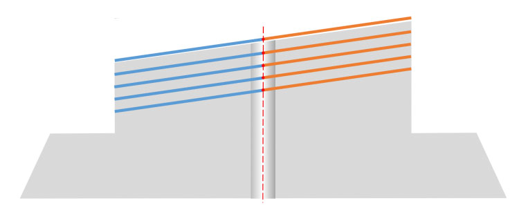
Figure 13: The midpoint location stays centered no matter how much material is removed.
When polished with a Radius, we can see that, like conical ferrules (see Figure 8), the ferrule Apex will also always be offset from the ferrule center.
However, because of the symmetry of the cylinder shape, this offset will be significantly less than with conical ferrules (Figure 14).
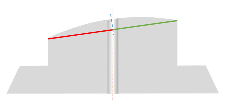
Figure 14: The Apex will be offset from the center point, but less so than with conical ferrules - and with the added advantage that it will remain constant regardless of how much material is removed.
We still have an inherent Apex Offset when polishing a domed surface on a step ferrule, but this offset is minor and a standard 8-degree polishing fixture can be used.
Step shape and Angle
We know that the Angle at the fiber region will always be less than the Angle we are polishing at – this is true of both conical and step ferrule shapes. But as with Apex, the magnitude of the difference is much less when using step ferrules. Because the ferrule Apex is closer to center, the difference in Angle will be significantly less – negligible, in fact. And, as with Apex, the Angle at the ferrule center will not change regardless of how much or how little we polish.
Radius effect on Angle
This effect is exactly the same as with conical ferrules (see Figures 11a and 11b), and the same rules given in that section apply to step ferrules.
Conclusions
Controlling Apex and Angle on conical ferrules is much more difficult than with step ferrules, namely because we need to control the “depth of cut” – the amount of ferrule material we remove during the polishing process. This means we must ensure the polishing films we use have exceptional lot-to-lot abrasive consistency. Also, since the abrasive cut-rate of polishing films declines the more times we use the film, we will likely need to reduce the number of times we reuse the films in our process (this will increase polishing costs). Because the step ferrule is unaffected by depth of cut, abrasive cut-rate variation has much less effect on our results.
With both conical and step ferules, the Radius we generate has a similar effect on measured Apex and Angle. In general, targeting a Radius at the lower end of our tolerance limits will improve our chances of acceptable Apex Offset and Angle measurements.
______________________________
1 Telcordia GR-326; IEC 61755-3-2
2 This statement is a bit of an oversimplification. There are other factors that certainly can and do affect Apex Offset and Angle values on both PC and APC polishing such as imperfections in material or equipment, errors in measurement, process errors made by operators, etc. Our discussion is focused on the concept of generating a radiused Angle through an APC ferrule and how our polishing process, in ideal conditions, affects the resulting Apex Offset and Angle measurement values. So, for simplicity, we will ignore such non-process-related factors.
3 The images of the conical and step ferrules show unpolished ferrules – there is no Angle yet generated on the tips. Both types of ferrules are available to purchase as “pre-angled,” where the ferrule manufacturer cuts the angle already. This significantly reduces polishing time and costs for the cable assembly. Whether using pre-angled ferrules or not, however, the same factors affecting Angle and Apex discussed in this paper apply.
4 The term “Apex” is generally understood to mean “the highest point along a surface.” But we need to understand that “highest point” is a RELATIVE term. Highest, in relation to what? Let’s use an example of an orange traffic cone. Imagine placing the cone on the floor and standing over it, so you are looking straight down on the cone. From this position, you could say the Apex of the cone is the point closest to your face. But what happens when you kick the cone over onto its side – essentially tilting it 90 degrees? Now the point closest to your face is not the tip of the cone, instead, it’s the edge of the cone’s base. You did not change the location of the Apex point on the object (the cone), you only changed its relative position in space from where you are measuring (your eyes). Thus, in our discussion, we need to be careful to distinguish between the FERRULE’S Apex (the highest point on its Radius, relative to the Angle to which it was polished) and the MEASURED Apex (the point on the ferrule surface closest to the interferometer camera during testing). This is particularly important when discussing conical ferrule polishing, as the angle at which we polish the ferrule and the angle at which we measure the ferrule are not the same – we essentially “kick the cone over” a bit during measurement.
Additional resources from the FOC team include:
- View Polishing Technical Solution Content
- View the Glossary, Acronyms, Military Specifications for Connectors
- Q&A Resource: email technical questions to AskFOC@focenter.com
This article is an original publication of Fiber Optic Center, Inc. It is shared publicly for educational and reference purposes to support learning and professional development within the fiber optics industry.
You are welcome to read, cite, or reference this material for non-commercial and educational purposes, as long as full credit is given to Fiber Optic Center, Inc. and the author.
Reuse, reproduction, or adaptation of this content — including rewriting, republishing, or incorporating it into new materials (such as websites, blogs, marketing text, technical guides, or AI-generated content) — is not permitted without prior written consent from Fiber Optic Center, Inc.
This material is protected by copyright law upon publication, even if not formally registered.
Use of this content for AI training, automated data extraction, or derivative content generation is prohibited.
Fiber Optic Center monitors and enforces the integrity of its intellectual property through digital identifiers and content tracking.
For more details, please refer to the Fiber Optic Center Content Use and Copyright policy.


