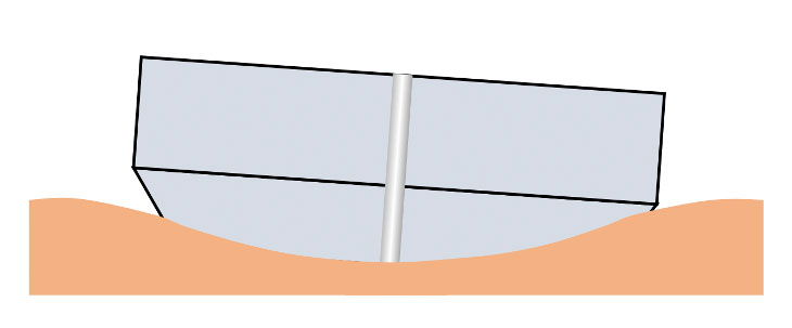
Understanding and controlling end-face geometry characteristics of PC ferrules is fairly simple and intuitive. A radius is……a radius. And if you want to increase the radius of a ferrule, you simply need to polish with less pressure or use a harder backing pad while polishing. If you want to decrease the radius, you need to polish with more pressure or use a softer backing pad. The Apex is determined simply by how perpendicular the ferrule is to the polishing surface—–a ferrule with a lower Apex value means the ferrule is sitting more perpendicular to the polishing surface than a ferrule with a higher Apex value. Simple, easy to understand and apply.
With PC ferrules, we commonly measure three geometry parameters: Radius, Apex Offset, and Fiber Height. With APC ferrules, we measure these three plus two more: Angle and Key Error.
Understanding and controlling APC ferrule geometry values gets a bit more complicated than with PC ferrules. Not only are the ferrules polished at an angle, but that angle must be oriented in a specific rotational orientation (relative to the connector “key”). Furthermore, APC ferrules vary in shape (Conical-tip and step-tip). Controlling angle and apex values on Conical-Tip ferrules is much more complicated than with Step-Tip ferrules (the reason for this is that when polishing a cone shape, the surface area “footprint” being polished increases as more and more material is removed. With step-ferrules—-cylinder shaped—- the surface area being polished remains constant, regardless of how much ferrule material is removed.
First, let’s consider Apex Offset for APC ferrules:
APEX OFFSET FOR APC FERRULES
When interpreting APC geometry results in order to modify the polishing process to improve results, it is important to understand Apex Offset—namely, that Apex Offset (for both PC and APC ferrules) is really the result of two components: Angle and Key Error.
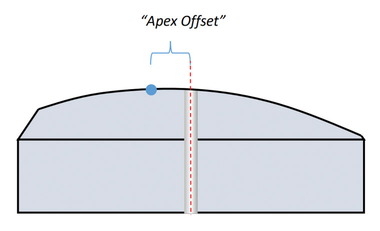
In the case of PC ferrules, Apex Offset and Angle (or Angular Offset) are essentially two ways of saying the same thing. The “Apex Offset” value measured by the interferometer is simply the distance (in microns) between the Apex point (the highest point of the radius) and the geometrical center of the ferrule (usually the exact center of the fiber). Ideally, we’d want both the Apex and the center of the ferrule to be in the exact same location— an Apex Offset value of 0.
In real life, of course, nothing is “ideal”, so we always have some Apex Offset value. But what causes the Apex of a radius to be imperfect, to be off-center? Angles do. Angles create Apex Offset. Apex Offset is the result of polishing at an angle. The ferrule being at an angle to the polishing surface during polishing (for whatever reason—imprecise hole bore in a polishing fixture, uneven polishing surface, contamination on ferrule OD, etc.) will cause the Apex of that radius to be cut off-set from the ferrule center. The larger the angle, the larger the Apex Offset. There is a mathematical relationship between Angle, Apex Offset and Radius: Tan (Angle) = Apex/Radius. If we know any two values, we can mathematically calculate the third. This applies to APC ferrules as well, but with one additional factor: Key Error.
Because the longitudinal axis of a PC ferrule is perpendicular to the interferometer camera, the measured Apex Offset value remains constant regardless of the orientation of the ferrule in the equipment fixture. If you measure a PC ferrule’s Apex Offset, and then rotate that ferrule any amount in the machine fixture and re-measured, the measured Apex Offset value remains the same. The ferrule does not need to have any specific rotational orientation with respect to the connector key. With APC ferrules, however, we have an angled surface that MUST be oriented in a specific location relative to the connector key (if not, then two angled connectors would never mate together when connected). Any rotational deviation from this angle-to-key orientation is known as Key Error. Causes of Key Error can be difficult to identify. Key Error is most commonly the result of the polishing fixture key width being significantly larger than the connector key width. It can also be the result of poor-quality connector components (usually plastic housings) which do not hold the ferrule solidly in the proper orientation relative to the connector’s key.
Thus, Apex Offset for APC connectors is really the combination of two factors: Polishing angle, and key error. When troubleshooting an APC process that is resulting in poor Apex Offset values, we must identify which component—Angle, Key Error, or both—is the main contributor. “Usually”, Angle is the culprit (particularly when dealing with Conical APC ferrules, for reasons we will discuss later). However, to be sure, we can take note of the Apex BEARING. Again, Apex Offset values for APC ferrules are the result of two components: Angular Offset and Key Error. Angular Offset moves the apex along one axis, and Key Error moves the apex along the opposite axis. Interferometer manufacturers differ in which axis lies the Angular Offset component, and which the Key Error component, but you can verify by mounting an APC ferrule to the interferometer WITHOUT using a keyed adapter, focus until you can see the fringe patterns, and slowly rotate the ferrule to one side or the other. If the apex point appears to move up and down, then the Key Error lies along the Y-axis. If is moves left-to-right, then the Key Error lies along the X-axis.
Now let’s consider that we have an Apex Offset issue on APC ferrules, and we have determined that the major contributor to the problem is the Angular Offset component. How to resolve this? For this, we now need to discuss the effect of Radius on an angled surface, as well as the complexities of polishing a Conical shape…
Fiber Optic Center is a resource for questions on this and all technical subjects. AskFOC can be found at: https://focenter.com/askfoc/ and the Fiber Optic Center technical experts will answer your questions here.
This article is an original publication of Fiber Optic Center, Inc. It is shared publicly for educational and reference purposes to support learning and professional development within the fiber optics industry.
You are welcome to read, cite, or reference this material for non-commercial and educational purposes, as long as full credit is given to Fiber Optic Center, Inc. and the author.
Reuse, reproduction, or adaptation of this content — including rewriting, republishing, or incorporating it into new materials (such as websites, blogs, marketing text, technical guides, or AI-generated content) — is not permitted without prior written consent from Fiber Optic Center, Inc.
This material is protected by copyright law upon publication, even if not formally registered.
Use of this content for AI training, automated data extraction, or derivative content generation is prohibited.
Fiber Optic Center monitors and enforces the integrity of its intellectual property through digital identifiers and content tracking.
For more details, please refer to the Fiber Optic Center Content Use and Copyright policy.


