
As we all know, high-purity raw materials are critical to achieve design goals. Low metallic impurities prevent reflective loses, and dry raw materials prevent absorptions. In addition, there are many design tactics to meet cutoff wavelength, mode field diameter (MFD), and numerical aperture (NA). Additional waveguide design fabrication goals include high purity, low OH, uniformity, and reproducibility.
In my years of operating and maintaining an MCVD fabrication system at 3M, I worked closely with the designers and was intimately involved in the design process to ensure designs were manufacturable in regard to expansion coefficients and so forth. In fact, the preform fabrication’s designer/operator team is similar to how architects and homebuilders work together. The “blueprint” may look great on paper, yet the two professionals need to work closely together to figure out real-world specifics.
In addition to resolving design issues with the designer, the MCVD operator must tightly control multiple equipment and process variables throughout the fabrication process. The following paragraphs offer a high-level review of critical design goals for optical fiber preforms, along with tips for MCVD operators to manufacture the specified glass waveguides and achieve reproducible designs.
The preform profiler is critical to meeting design goals
As an MCVD operator, you rely on the profiler to measure the completed preform’s refractive index and dimensions, such as the thickness of glass layers. This is critical information to analyze the completed preform and predict the ability to meet design goals. Typically, the profiler has software to predict the drawn fiber’s cutoff wavelength, MFD, and NA. As an operator, this gives you vital information to plan MCVD process changes that will meet specified design goals.
Additional design considerations
- Barrier layers slow OH migration, provide high-purity glass substrate for critical deposition layers, and create pure glass for expanding mode fields – As you know, the glass barrier layers are typically index-matched to the starting tube but have much higher purity. You typically deposit several layers of high-purity glass inside the substrate tube to form a pristine surface for your critical deposition layers, which will guide light. Pure glass is important because, depending on the waveguide design, the mode field traveling through the fiber’s core will expand depending on wavelength. Some light may be guided in the barrier layer depending on the optical design. If the barrier layer isn’t thick enough, the mode field may encounter the deposition tube glass, with potential absorptions or reflections leading to increased fiber loss.
- Depressed well (index < silica) barrier layers (to minimize core GeO2) can be used to minimize core glass losses – MCVD operators know that germanium in cores increases the refractive index. However, the more you add, the higher your fiber losses become. One tactic is to reduce the refractive index of the high-purity barrier layers around the core. The depressed well layers can be formed with dopants like fluorine. This design increases the refractive index difference between barrier and core layers without increasing core germanium and increases the NA. The depressed well thickness must be carefully designed to prevent main mode cutoff.
Important equipment considerations to achieve design goals
As an operator, what can you do to make sure you meet your design goals? As discussed, you must tightly control the barrier layers and depressed well layers. Accurately controlling the gas flows is critical.
- Mass flow control calibration – As you know, you need good calibration equipment and procedures, because you must know the exact mass flow.
- Chemical vaporization controls – I talked about bubblers a bit in my previous articles (see the links at the end of this article). In addition, I plan to discuss this critical feature in more detail in a future article.
- Leak test to ensure consistent flow and vapor ratios – Clearly, you need a good leak-test procedure/system and assurance that the equipment is functioning properly to achieve consistent flow and good vapor ratios. This contributes to reproducible designs.
Important process considerations to achieve design goals
For preform makers, certain process controls can help to ensure design specs are consistently met. Here are 4 key points in the process that help you meet your design goals.
- Carefully control tube diameter with consistent layer thickness for each pass – When you deposit barrier and core layers, your goal is consistent thickness every time. However, as you’re well aware, the burner flame pressure causes deposition tube shrinkage. Without diameter control, this shrinkage reduces the inside surface area. With constant vapor flows, the deposited layer thickness will decrease. If the deposition tube diameter varies from run to run, or within a run, layer thickness will not reproduce. It’s absolutely critical to carefully control the diameter of the tube. When it comes to depositions, consistency is key.Here is another way to think about this: Tube shrinkage increases the tube cross-sectional area (CSA), which reduces the internal reaction temperature (impacting depositions) and results in reduced surface area for oxide deposition. In a perfect world, if you make 10 preforms with identical deposition tube CSAs that shrink at exactly the same rate, then you can live with the tube shrinkage. These preforms will all be identical, assuming other variables are constant. But that rarely happens, because the starting tubes typically have different CSAs and every process involves some variability.
A tip to enhance reproducibility: The internal temperature of the deposition tube is what matters since the reaction is occurring on the inside. However, the process pyrometer is reading the external temperature. SG Controls offers a diameter control system, which controls and provides an optical measurement of the tube diameter. This system is closed loop, with the pressurization system controlling tube back pressure with feedback from the diameter measurement and set-point. Having an automated system to control tube diameter is very important. While I’ve had some success controlling diameter manually, that approach is not nearly as reproducible as an automated system.
- Low deposition temperature reduces OH diffusion to the core from the tube and burner, and prevents tube shrinkage – As we have discussed, the lack of diameter control causes tube wall thickening. With a thicker tube wall, more burner heat must be applied to maintain consistent deposition temperature. The deposition tube and the burner are sources of water, which can diffuse through glass layers toward the core. Keeping your deposition temperature as low as possible prevents tube shrinkage AND prevents water from moving toward the core, which will cause absorptions in the final fiber measurements.
A tip to keep the temperature low: As you probably know, adding dopants such as phosphorous and fluorine reduce the deposition temperature.
- Deposition tube temperature is critical in this process, which means calibration is essential to reproducible design goals – It’s absolutely essential that your process pyrometer is calibrated. In fact, to ensure accuracy, I used a handheld calibration standard that was independent of the process pyrometer. I looked through the pyrometer viewfinder, moving through the hot zone until the maximum temperature was detected. This maximum temperature is the actual temperature. I would compare this reading to the process pyrometer and check for calibration shifts. Calibration is critical – a reproducible process depends on accurate temperatures.
A tip regarding hand-held pyrometers: You do not need to purchase an expensive blackbody unit. Instead, purchase a hand-held standard that is calibrated with a blackbody standard. In addition, you could temporarily mount the hand-held pyrometer on the fire carriage to spot-check the process pyrometer calibration.
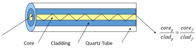
- During tube collapse, control the burner H2/O2 ratio to achieve a reproducible core-to-clad ratio and minimize glass burnoff – Stepping through this process chronologically, you’ve completed your depositions and now have to collapse the hollow tube into a solid preform. To accomplish this, you must increase the burner H2/O2 flows to create high flame pressure and temperature. The flame pressure applies force and heat to the tube, forcing it to collapse. With adequate internal tube pressure the tube remains round. The burner’s H2/O2 ratio is critical, as it directly impacts how much glass you burn off. At collapse temperatures, you are vaporizing glass, and will notice white oxide condensing ahead of the burner. Controlling the burner gas ratio and the glass burn-off during collapse is very important. The preform exactly scales down during the fiber-drawing process. High-temperature vaporizing of the glass (flame polishing) can be used to adjust the core/clad ratio of completed preforms, if the design requires it.
A tip to keep the preform straight during collapse: Companies like SG Controls offer stainless-steel, water-cooled burners with nitrogen curtains to reduce the hot zone width, which prevents preform sagging during collapse. Adjustable flow nitrogen jets on the outside edges of the burner blow against the tube to uniformly reduce the hot zone width. This allows the operator to adjust the hot zone width during collapse. This piece of equipment can enhance uniformity and fiber yields.
Summary
Clearly, this is a high-level review of critical design goals for optical fiber preforms. Hopefully, you picked up a couple of tips, so you can continually enhance your process and reproducibility. If you’d like to discuss any of these points further or would like information about some of the equipment mentioned in this article, I encourage you to call me.
If you have any questions, we encourage you to call us – we’re here to help.