Purchasing high-purity raw materials is critical to manufacturing quality preforms. How we handle our materials, tools, and equipment is equally important. For example, properly purging gas cylinder connections, properly filling reagent bubblers, and properly cleaning deposition tubes will enhance your fiber yields.
If you are an MCVD operator I’m certain you recognize that spending time and attention on each preparation step will prevent issues later in the fabrication process. Issues such as deposition bubbles, soot collector joint bubbles or cracking, and fiber strength problems can be prevented. The following paragraphs present key preparation steps and offer tips, which I hope will help you enhance reproducibility and fiber yields.
The quartz tube-cleaning process
Properly cleaning deposition tube assemblies (the tube and extension tube fused together) to remove contaminants from the internal and external surface will increase fiber strength and prevent bubble formation during deposition.
The tube-cleaning process is a critical part of your preparation. Companies like SG Controls offer tube-cleaning machines with programmable cycles. The first ingredient needed is a high-purity source of deionized water for rinse cycles. Typically, an 18-megohm purity level of deionized (DI) water will ensure there are no impactful impurities.
MCVD operators apply various approaches to the tube-cleaning process. I find that using the first cleaning step to remove metallic impurities works well. If you were to HF etch first, you may etch the glass around the metallic impurity, but not necessarily remove it. If you only HF etch, some metallic impurities may remain. For the first step aqua regia can be used – an acid mix of hydrochloric acid, nitric acid, and water. A typical acid cleaning cycle is 30-60 minutes with aqua regia to remove the typical metallic impurities, followed by a DI water rinse. You may want to adjust the time depending on your process.
The next step is to etch the glass surfaces, cleaning the inside and outside. Most MCVD operators use hydrofluoric acid. A 15% concentration for 30-60 minutes is a good starting point. You may want to adjust the time and concentration for your process. Follow this etch cycle with a final DI rinse and dry with nitrogen to prevent water spotting.
Normally a weekly supply of tubes is cleaned and must be stored in a clean cabinet to prevent contamination. The cabinet is typically in a clean air room, or the cabinet is purged with filtered nitrogen to maintain a cabinet positive pressure.
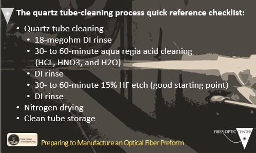
For your quick reference, here is a checklist of the steps discussed above:
- Quartz tube cleaning
- 18-megohm DI rinse
- 30- to 60-minute aqua regia acid cleaning (HCL, HNO3, and H2O)
- DI rinse
- 30- to 60-minute 15% HF etch (good starting point)
- DI rinse
- Nitrogen drying
- Clean tube storage
Loading the tube onto the lathe
The final tube preparation for the first deposition passes is performed once the tube is loaded onto the lathe. Initially, the deposition tube is secured by the headstock lathe chuck. The rotary seal is attached to the input extension tube (previously fused onto the deposition tube). While rotating the lathe at approximately 40-50 RPM the rotary seal extension tube should have only a small amount of runout to prevent seal movement, possible connection leakage, and potential tube cracking. If there is significant runout, the handle should be straightened before proceeding with the setup. Failure to correct this can cause issues during the deposition process potentially leading to a lost fabrication attempt.
Initial deposition tube straightening
Initial deposition tube straightening is performed to minimize runout. Carefully using a hand burner at a low temperature will prevent vaporizing glass at straightening points. Fusing the deposition tube to the larger soot-collecting tube is typically done with positive internal tube pressure. The glass joint is expanded during the fusing process to form a uniform glass transition thickness.
I would like to elaborate on initial tube straightening. You now have the tube in the lathe. It is attached to the rotary seal and the tailstock end is hanging free. I typically start by heating the headstock end very gently with the hand burner while supporting the deposition tube end with a V-shaped graphite paddle. You may need to straighten multiple locations along the tube.
The exhaust tube is clamped into the tailstock chucks, and it should also be straightened to eliminate runout. Next, I fuse the deposition tube to the exhaust tube, which has a much larger diameter and must be paddled down with a graphite tool. The lathe pressure control system is used to control internal tube pressure as you heat and fuse the joint. I expand the joint and allow it to shrink down slowly to achieve a very gradual transition between the two diameters. All vapors/oxides that are not reacted/fused are exhausted out to your scrubber. If you have a thickened joint area, unfused oxides can condense, potentially plugging the exhaust tube and/or forming cracks. Taking the appropriate time to properly form joints can prevent lost fabrication runs.
The final tube straightening/stress-relieving process
MCVD operators use a variety of techniques for the final tube straightening process. I found that straightening from the tube center toward both ends works well. I like to start by removing the runout from the tube center point. I initially heat the headstock and tailstock ends simultaneously, with one end much cooler, and holding a graphite paddle at the center point until the tube runout is eliminated. One end is then heated (with the center very lightly heated) while I hold the paddle at the end of the first straight section to eliminate runout. The hand burner is then moved to the last graphite paddle location and the paddle moved to the next straightening point until one half is straight. These steps are repeated for the other half of the tube.
There is one final step, which I call stress relief. Some stresses may have developed during the straightening process. When your burner initially heats up at the process start point the tube could sag.
To prevent this possibility I heat the headstock end very warm and look for tube sagging. If sagging occurs, the exhaust end is lightly heated while supporting the headstock end to eliminate runout.
Flame polish
The final step prior to the first deposition pass is a high-temperature (~2000 degrees C) flame polish. The polish is typically performed with a positive internal tube pressure to prevent shrinkage. The polish step vaporizes a minimal amount of glass from all surfaces to ensure there is a pristine surface to deposit initial deposition layers.
A helpful tip: Fluorine gas can be introduced to assist with glass vaporization (internal surface layer removal) to provide a very clean surface for deposition. In addition to the oxygen flow for pressure control, fluorine gas will accelerate glass vaporization at high polish temperatures. This final preparation step will provide a pristine surface to prevent deposition issues, such as bubbles, and potential weak final fiber.
Chemical bubblers
Once the chemical bubblers are at proper levels and stable temperature the vapor deposition can start. It is important to ensure your bubbler temperature control can respond to flow changes and liquid levels quickly, to ensure a constant vapor stream for each deposition pass. If the programmed flow rate changes from low to high, or chemical levels drop significantly, bubbler temperature may drop and reduce the vapor pickup rate.
To prevent this, companies like SG Controls offer isothermal immersion heaters for fast response to a chemical temperature drop. These systems will control temperature drop to less than 0.3 degrees C with complete temperature restabilization in just a few minutes. This isothermal immersion heater and temperature probe are located in dip tubes, measuring the actual chemical temperature, not the oil bath temperature. This heater reacts to any change the dip tube thermometer reads and compensates. This additional control system can restabilize the chemical temperature in less than 5 minutes (typically one clearing pass). This added bubbler feature overcomes bubbler temperature drop due to latent heat of evaporation. In addition, variations in vapor pickup associated with re-equilibrium along a deposition pass are eliminated.
If you have any questions, we encourage you to call us – we’re here to help.