Fiber Optic Center will be at Anga Com - Schedule your meeting with a member of the FOC team now
As Published in Euro Wire May 2013, Wire Journal International July 2013 and Wire Asia July 2013
Reprinted in Proceedings of the 61st IWCS Conference; International Wire & Cable Symposium
Reprinted in Proceedings of the 61st IWCS Conference; International Wire & Cable Symposium
From Optical Cable to Optical Wire – An Evolutionary Approach
Abstract
This presentation will introduce a new design in optical fiber cable that allows small form factor cables to have handling characteristics that are as good or better than copper wire. Currently, most lightguides are housed in cable designs that follow an orthodox design protocol based on one of three basic cable types: loose tube, ribbon or tight buffer. All require very specific handling techniques that require special care and simply cannot be handled the same by installers who are accustomed to handling copper. Yet, the need for a fiber to act more like copper is becoming more and more apparent as cable sizes decrease and applications, such as central offices, data centers, enterprise, fiber-to-the home/desk (FTTH/D), demand more fiber density. A fiber cable with the behavioral characteristics of a copper cable will improve installations in terms of time, flexibility and cost.
Keywords: Optical patch-cord, simplex cable, duplex cable, optical wire, micro-cable, small form factor, interconnect cable.
1. Introduction
Many new optical fiber cable developments have occurred in the recent past, such as reduced bend radius fiber (RBRF), nano-composite material fillers, new materials for strength, connector technology, new regulatory compliance issues (ROHS, REACH), and size/cost constraints. During this time, cable design solutions assumed fiber-optic cable to be a composite product where separate elements (Tight buffered fiber, aramid yarn polymer jacket) were not bonded. Therefore, different handling and installation requirements were mandated based on a non-coupled core structure. In many cases, installation stresses were overcome by sheer bulk or material strength.
Many analog comparisons to copper have been made in the cable world. Other than specialty products, such as guided torpedo fibers, no true optical analogs to wire have been developed.
Typically, cables contain one or more insulated conductors and additional structural elements to achieve mechanical, environmental or other performance criteria. To date, most optical fiber designs use a “loose core” to achieve engineered performance in an optical cable - even single fiber cables that require minimal protection. The result is that many designs require installation handling different from traditional copper cable installations. Many failures are a direct result of installer unfamiliarity with the special handling required by traditional indoor simplex or duplex fiber cables. Thus, the need for a fiber to act more like copper in terms of handling is important as fiber adapts to use in applications where copper once was king.
There is a perception by many installers that fiber can be handled and installed using the same methods as its copper predecessor. However, glass is still glass, and the performance of traditional fiber cable can still be affected by improper handling and installation.
So, why does this perception matter? In today’s environment, optical system solutions are being provided to a much broader selection of customers. Many of these installation professionals have significant experience with copper installation practices. Yet they are, for the most part, unfamiliar with the installation practices of the fiber cables they are now being asked to install. Thus, it is incumbent on fiber cable manufacturers to educate them on acceptable handling practices. More importantly, to improve the acceptance of optical fiber systems in new applications, we must provide products that will succeed under new criteria. In terms of optical fiber cable, we must design products that behave closer to copper insulated wire in fiber cable handling, placement and management.
New optical waveguides have made this option viable, but we as cablers need to continue the evolution and design installable “cables” (wires) that meet customer needs and define a new class of optical waveguide product.
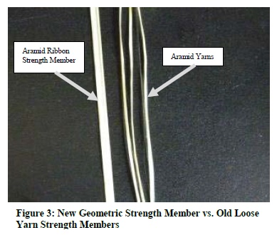
The design presented here is a geometric core design whereby the optical fiber is located in the center of the core and loose yarns have been removed in place of geometric strength members. These strength members provide multiple functions, such as outer jacket adhesion (to assist with hand pulling) fiber buffering (against impact and crush loads) and reliable access to the optical fiber for fusion splicing or field connectorization. As with all communication devices, improved performance must be accomplished while ensuring affordability. Designs that meet these new requirements but are costly and hard to produce will not succeed. The cable must also be able to be mass produced on typical cable equipment with acceptable yields and quality performance.
2. Challenges to “Optical Wire”
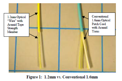
Traditional simplex / duplex optical fiber cables, developed over the past 30 years or more, consist of a loose tube design with Aramid yarns for strength. The glass fiber is embedded in the center of the yarns with a polymer tight buffer coating to prevent severe bending or impact. Aramid yarns are deployed so that both ends can securely attach the connectors. Thus, if a connector is pulled, it is the non-stretching yarns that are actually being pulled and not the fiber or jacket itself. The challenge in strengthening the fiber cables this way is that if we pull them by the insulation as if they were copper wires, we’re actually pulling on a piece of polymer plastic with very little strength. Pulling the fiber jacket temporarily stretches the polymer while the glass length remains constant. This causes a mechanical decoupling of the fiber from the strength members and polymer jacket and allows a bunching of the outer jacket and allows a unplanned movement of the buffered fiber to cause excess length on one side of the pull and a tensile condition to occur on the other. This typically results in large macro bend losses as well as possibly exceeding the minimum bend radius of the optical fiber. This can shorten the life of the cable significantly.
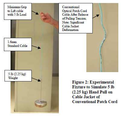
When developing 3-mm fiber cables, the jackets were relatively thick – in some cases, almost a millimeter thick. This provided a bit more intrinsic strength in the plastic polymer before it was stretched. And early installers were more concerned with handling characteristics. Today, the demand is for density, so fiber cables are becoming as small as possible. This has two results. First, cable jacket thickness is becoming as small as possible and, second, the cables are being pulled with more strength to fill raceways and conduits with more fiber. Both of these issues can affect reliability and performance of the fiber.
As the smaller fiber cables are pulled, the jackets are stretched. As they shrink back over time, enough friction is generated to push the buffered fibers back. This action results in a localized area of excess fiber, known as a microbend, as the jacket shrinks. As optical cable sizes were reduced to 1.6 millimeters, this phenomenon was caused by as little as a few ounces of force instead of pounds. Thus, as optical cables became smaller, more delicate handling was required during installations. This new category of cables became known as “small form factor” cables because they could no longer pass the same testing as their larger counterparts. Tensile gradings went from 22 pounds to nine pounds, allowing minimal amounts of Aramid yarn and decreased jacket thickness. But it also resulted in products that required much more care in handling than any copper wire.
The challenge was to develop a new fiber cable design for small form factor products that could meet the requirements for more density while providing wire-like strength that would allow it to be handled and pulled without causing attenuation and other performance issues. The challenges were met by solving three major issues – strength, connectivity and thermal balancing.
3. Achieving Copper-Like Strength
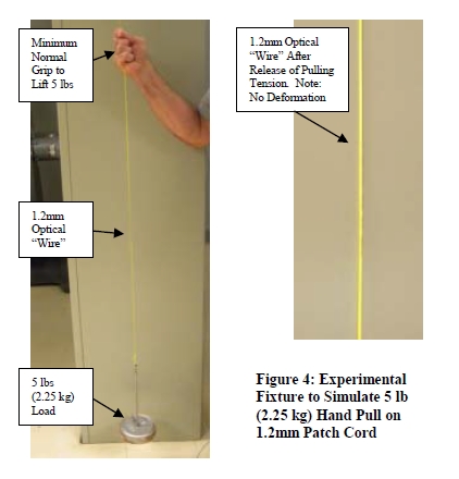
To provide the strength of copper in a 1.6-mm fiber optic cable was the first challenge. Installers should be able to pull the cable in a straight line like copper wire without needing to wrap it around a mandrel to keep from damaging the jacket. At the same time, the jacket must be about one-third the size of conventional jackets. The free space around the glass needed to be reduced to make the cable as small as possible. Yet, the cable had to meet all impact, resistance and crush strength testing.
As small form factor cables are handled, the fiber can actually migrate to one side or the other of the jacket as the loose yarns give way. Once that occurs, the fiber is less protected on one axis and no longer provides the protection that was conceptually designed into it.
By using a tape with an adhesive matrix material, a custom tooling was designed to wrap several times around the fiber in a longitudinal fashion. The longitudinal tape wrapping ensures the centering of the fiber while only a very thin outer jacket bonds to the tape. This bonding allows installers to perform reasonable hand pulling or hand setting of the cable without stretching the jacket. By enabling the tape and jacket to bond as a single entity, the fiber cable could be handled much like a piece of copper wire in terms of strength.
While many micro-cables are available today, they typically use Aramid yarns intertwined around the fiber. None have actually coupled the yarns, jacket and fiber together. This cable is unique because it uses an Aramid tape instead of loose yarns. The tape can also be stripped using conventional copper cable stripping machines or copper wire stripping machines. Lineman’s scissors can even be used to strip these cables – the first time this has been achievable with a coated fiber without requiring a specialized tool.
It should also be noted that RBR Fiber, rapidly becoming the standard in FTTX solutions and central offices/data centers, also add to the handling qualities of these new fibers. Smaller cables can be bent around tighter configurations to fit various types of modules and installations.
4. Connectorization
The bonding of the tape and jacket, however, created a new challenge with connectorization. Bonding the two together eliminated the space required for the fiber to “push back” from the connector. Therefore, connectors had to be re-designed specifically for use with these new fibers. These new connectors take into account that the fiber has no push back, or compression capability, within the jacket.
Traditional fiber cables allow the fiber to slide back in the jacket enough for connectors to be attached, sometimes as much as two millimeters. Thus, connectors were designed with backshells that can account for the lack of additional empty space in the cores. These connectors still conform to GRS 326 performance levels or higher.
5. Thermal Balancing
Finally, since the tape and jacket are bonded together around the glass, thermal performance balancing was required to enable the entire cable to perform under standard thermal conditions. Each material – glass, tape and jacket – has a different level of thermal coefficient of linear expansion. This means that each material within the cable will expand or contract at different rates under different temperature conditions. For example, plastics typically expand and contract up to two orders of magnitude more than glass.
In designing this new fiber, Aramid yarn was known to have a negative coefficient of linear expansion. But bonding everything together, most of the effects of thermal coefficients of linear expansion were virtually neutralized. In the end, the cable behaves very similar to the actual glass in terms of expansion and contraction, performing from -40 degrees Celsius to 70 degrees Celsius with minimal attenuation changes. Conventional plenum rated cables typically perform from 0 degrees Celsius to 50 degrees Celsius – as required by plenum cable standards.
6. Conclusions
As optical fiber solutions evolve to areas where copper once ruled, the importance of having the same handling, installation and management characteristics as copper wire cannot be underestimated. Optical cables need to have enough strength to be pulled, twisted and cornered similar to copper without affecting performance.
By designing new cables that eliminate air and space inside the cable, smaller footprints can be achieved. Replacing the loose Aramid yarns with tape wraps and bonding the cable elements together is enabling a new evolution in small form factor optical micro-cables. This, in turn, will expand the available system solutions to a broader section of customers, while providing optimal density, flexibility and performance of fiber in enterprise applications.
7. Acknowledgments
The author would like to acknowledge the help of Ken Nardone, Henry Rice, Bill Jacobsen, and Aly Fahd in obtaining data and test information for this paper.
8. References
TIA-455A Fiber Opt8ic test procedures
Telcordia GR-409-core issue 2
Telcordia GR-326-core issue 4
ITU 657.A 2009-11
Reliability of Bend Insensitive Fibers; Willem Griffoem Draka Communications, Proceedings of the 58th IWCS Pages 251-257 2009
Macrobending Loss in Bend Insensitive Fibers: A Statistical parameter? Susanna Cattelan, Prysmian SpA, Proceedings of the 58th IWCS Pages 258-263