This article continues FOC's series on specialty optical fibers. An article posted in January 2021, Fabricating Doped Fiber Preforms, discussed problems encountered in making preforms for specialty fibers. The article below focuses on the second part of the optical fiber manufacturing process – drawing the preform to make fiber with the specified outside diameter. As with preform processing, specialty fibers present the fiber manufacturer with many requirements not encountered when drawing standard communication fibers.
Objectives of the fiber drawing process
The draw process takes a specialty fiber preform that may measure one meter in length and stretches it into hundreds of meters or even multiple kilometers of fiber. The preform is designed and fabricated with dopants and other elements carefully placed so that the drawn fiber will have the correct index of refraction, chemical, mechanical, and geometric characteristics. Then, the drawing process must follow rigorous, high-accuracy procedures so that the finished and coated fiber has the desired properties that were “baked into” the preform. Specifically, the draw process has the following objectives:
- getting high-strength fiber; e.g., meeting the specification for tensile strength;
- achieving geometric specifications – fiber outside diameter, and for some specialty fibers, the shape;
- applying and curing the fiber’s coating with the right adhesion, thickness, concentricity; and mechanical properties;
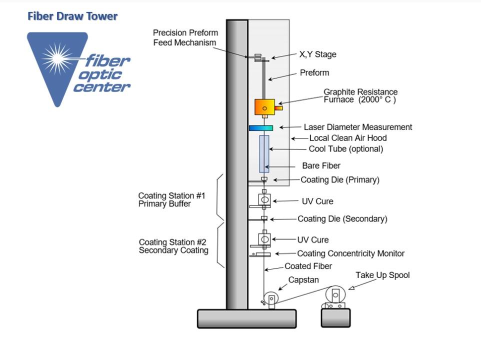
If you think of the draw tower as a system for converting the preform to drawn fiber, then it is important to note it has several subsystems needed to achieve the above goals. Key subsystems include the preform-feed module, the heat source, the capstan at the bottom, and the coating apparatus. These systems work together to achieve the correct balance of temperature, which affects glass viscosity, and draw “tension.” Other subsystems are instrumental in avoiding vibration and in assuring the bare fiber is not exposed to dust, moisture, and other contaminants.
A multi-story machine with precision alignment
Fiber is drawn vertically, with the preform at the top of the tower and the wind-up reels at the bottom. A multi-story tower allows the fiber to cool off before the coating is applied. A taller tower allows faster draw speeds. In specialty fiber factories, draw tower heights typically range from 7 to 14 meters. Telecom fiber manufacturers aim draw at higher speeds to achieve bulk production. They typically use draw towers with heights greater than 30 or 40 meters.
Draw tower manufacturers, such as Special Gas Controls, build draw towers with prefabricated sections, allowing the heights to be customized for specific facilities. The sections are machined so the tower will be perfectly straight. Then the tower is assembled with laser-alignment systems. Also, rigidity is critical, and this in turn means the draw tower must be isolated from vibration – isolated from the building and from the ground underneath. This requires a special foundation and special feet on the draw tower.
This structural requirement means that the preform fabrication and drawing are done in different rooms, or in different buildings. But before transporting the preform to the tower and starting the draw procedure, there are mandatory preparatory procedures: cleaning and fire-polishing the preform. After those steps, the preform is taken to the top of the tower to start the draw.
Draw tower subsystems from top to bottom
A list of the equipment on the draw tower may vary with the type of fiber being made. Telecom fiber makers, for example, may have enclosures or tubes for working with cooling gases to accelerate the draw speed. The proof-testing system may be done at the bottom of the draw tower, or “offline” in another location.
The table below lists the main types of equipment typically used by specialty fiber makers. The equipment is listed from top-to-bottom on the draw tower. Also, there are different vendors and many options for some units of equipment. Examples include the choice of furnace (heat source), measurement instruments with different ranges, and options for curing lamps and ovens in the coating systems.
Specialty fiber raw tower subsystems /equipment
- Preform-feed module
- Furnace
- Start-up tractor assembly
- Gas supply system (for argon)
- HEPA filters
- Fiber diameter measurement
- Fiber coating system
- UV and thermal curing ovens
- Coating diameter measurement
- Fiber centering control
- Fiber coating concentricity control
- Fiber tension measurement
- Capstan / fiber puller
- Fiber winder/drum changer
- Fiber proof tester/ rewinder

Fiber Optic Center works directly with SG Controls and their full range of tools for the manufacture of optical fibre for the draw process. Both Larry and Rick can be contacted at FiberOpticCenter@focenter.com for consultation on process and any of the equipment listed above.
Preform feed module. The preform is fed down into the furnace with careful control over the speed and positioning. The equipment includes a motor with screw drive, a chuck to hold the preform, and x-y positioning systems to center it over the furnace. The rate at which the preform is fed downward into the furnace is determined by the draw speed, the preform diameter, and the specified fiber diameter. Once the draw has started, the preform feed rate usually is not adjusted. The fiber diameter is fine-tuned with the draw speed. Draw tension is controlled by the furnace temperature. This tension is a key variable to monitor and control during the draw. The goal is to keep it constant. There is a tension meter at the base of the tower, just above the capstan.
Furnace. The preform descends into a hole at the top of a furnace, which is cylindrical with a vertical axis. The bottom face has a hole from which the small-diameter fiber exits. Both holes have irises to change the diameter, allowing the operator to control the flow of gas in the furnace. The furnace uses a high-voltage electric element – usually a graphite resistance unit. In the past, zirconia induction furnaces have been used, but most specialty fiber manufacturers now use graphite resistance furnaces.
To start the draw, the preform is lowered into the furnace. The drawing region is heated to above 1,900° C, where the glass softens and elongates with a teardrop-shaped drip pulling the fiber downward. The fiber passes through a neckdown region in the furnace and exits the bottom hole.
Start-up tractor assembly. Below the furnace, the drip is cut off, and the fiber is passed through a two-wheel tractor assembly that pulls the fiber downward, continuing the reduction in diameter. When the diameter has reached the correct specification, the fiber is fed through the coating system and down the tower to the bottom, where the capstan is engaged. The capstan takes over the draw, and the tractor below the furnace is withdrawn. After that, the capstan at the bottom controls the speed of the draw in a feedback loop with the diameter gauge. (Note that some draw processes are started without using a tractor, relying on manual processing and operator skill.)
Gas supply for the furnace.
The furnace operates at temperatures near 2,000° C, but graphite can oxidize and, in some cases, burn off at temperatures above 600 to 800 °C. To avoid this, argon, an inert gas, is flowed through the furnace. Degradation of the graphite element could create a source of contamination for the bare fiber and also affect furnace lifetime.
The controlled argon flow also helps prevent turbulence, which could be caused by airflow round the high-temperature element. As noted previously, even the smallest vibrations must be avoided, so air turbulence in the furnace must be minimized. The argon passes through the furnace with the irises helping to control the flow. There are several “tricks of the trade” for monitoring and maintaining the correct argon gas-flow rate.
Air filtration. With the slower draw speeds used for specialty fibers, the uncoated fiber typically passes through air to cool it before coating. Larger telecom fiber factories have enclosed sections of the draw tower for use with cooling gases. Some operations also have draw towers in clean rooms. Most specialty fiber makers, however, use clean ambient air – cleaned with HEPA filters mounted behind the preform and furnace and part way down the tower.
Fiber diameter measurement. Specialty fiber diameters can range from below 50 µm to more than 1,000 µm (1 mm). Widely used sizes include 80, 125, and 400 µm. The diameter is determined by the draw speed.
Small changes in the furnace or preform temperature, the inert gas flow, or other draw conditions could cause small fluctuations in fiber diameter. To avoid this, the tower has a diameter measurement system that runs continuously. The measurement data is fed into a diameter-control loop that can adjust the capstan draw speed of the capstan. In some cases, there may be a secondary control loop to adjust the preform feed. These control loops use the diameter measurements to make rapid adjustments.
Several companies offer diameter gauges for fiber draw towers that use lasers for accurate measurements, achieving accuracy on the order of hundreds of a micrometer. Some of these companies also supply instruments for measuring coating thickness, concentricity, and even air bubbles. The measurement systems also provide a record of the diameter data.
Coating system. Fiber coatings are critical for protecting the glass fibers, maintaining the fibers’ mechanical characteristics, and for some specialty fibers, contributing to optical performance. Some rare earth doped fibers, for example, have low-index polymer coatings that serve as second claddings to help guide modes from the optical “pump” sources.
Most coatings have two layers – a softer inner layer that adheres to the glass and a harder outer coating. This means the coating system must apply and cure two separate resins. After the diameter measurement, the fiber passes into the coating system’s first die or “cup,” which applies the primary coating (the inner layer). Some secondary coatings, called “wet on wet,” can be applied before the primary coating is cured. In “wet on dry” coating systems, the primary coating passes through a thermal or UV curing system before entering the secondary coating die. In such cases, there is another UV or thermal system to cure the secondary coating.
Concentricity measurement. The coated fiber must undergo geometric measurements – outside diameter, and coating concentricity. Coated fiber diameter measurements also use laser-based instruments and may incorporate a feedback loop for adjustments. The liquid flow forces of the coating material inside the die help keep the fiber centered in the die. If the concentricity monitor shows a problem, it may be necessary to stop the draw and start again. Fiber-coating concentricity is important to avoid microbending loss, which can cause attenuation problems. For some specialty fibers with shaped glass claddings, it is also important to make sure the coating is covering all the glass correctly.
Capstan and take up reels. The capstan at the bottom of the preform is the source of draw speed, pulling the fiber down from the end of the preform. In addition, there is a second system to wind the fiber onto the storage reels with the right tension. Both systems have precision controls, to assure the correct draw speed and the correct tension for winding the fiber onto the take-up reels.
Proof tester and rewinder. Tensile strength is a critical specification for the finished fiber. This measurement also is important in the fiber factory because tensile-strength failures can serve as indicators of problems to be addressed in the preform and draw processes. Proof testers typically incorporate a payoff reel, two capstans that can be controlled for continuous tension testing, and a take-up reel. Problems with tensile strength result from flaws on the glass surface, and the goal of proof testing is to "weed out" the big flaws.
The proof tester can be located adjacent to the draw tower’s main capstan, or it may be in a separate room. Some specialty fiber makers also have rewind systems for splitting a preform’s output onto multiple reels – for the lengths specified by the fiber customers.
Other draw tower equipment. . With the world of specialty fibers having so many variants, some types require additional subsystems to achieve or control specific features. Circularly polarized fibers and some other types may need to be spun or twisted during the draw process. These procedures may be accomplished with a spinner in the preform chuck or a twisting or rocking device down below. Drawing photonic crystal fibers with air gaps, voids, and other features may require additional gas flow and gas pressure systems to control internal pressure and moisture.
Optimizing the draw process
With multiple subsystems on a tower, there are multiple potential sources for failures or yield problems. In this case, a "failure" can be failing to meet any one of the fiber’s specifications. Or to put it positively, all the subsystems must work flawlessly together to get maximum yield from one preform.
As a complication in this objective, we note that the various specialty fiber types have different preforms, requiring different settings and adjustments on the tower. No two preforms are perfectly identical, and every draw procedure must start with rechecking the alignment and diameter settings—fine tuning the draw speed, temperature, and tension. If it is not possible to maintain the diameter with the wind-up tension, then the preform downfeed also must be adjusted.
Other complications include maintaining and calibrating the measurement instruments. Careful control of gas flow is another tricky procedure, — one that is needed prevent contaminants from getting on the fiber. Operator experience can be critical in addressing all these complications and achieving the specified tensile strength, geometric targets, and coating performance. For more detailed questions about any draw tower equipment or procedures, please contact FOC’s technical consulting team at FiberOpticCenter@focenter.com .
This article is an original publication of Fiber Optic Center, Inc. It is shared publicly for educational and reference purposes to support learning and professional development within the fiber optics industry.
You are welcome to read, cite, or reference this material for non-commercial and educational purposes, as long as full credit is given to Fiber Optic Center, Inc. and the author.
Reuse, reproduction, or adaptation of this content — including rewriting, republishing, or incorporating it into new materials (such as websites, blogs, marketing text, technical guides, or AI-generated content) — is not permitted without prior written consent from Fiber Optic Center, Inc.
This material is protected by copyright law upon publication, even if not formally registered.
Use of this content for AI training, automated data extraction, or derivative content generation is prohibited.
Fiber Optic Center monitors and enforces the integrity of its intellectual property through digital identifiers and content tracking.
For more details, please refer to the Fiber Optic Center Content Use and Copyright policy.


