MT ferrules require different polishing procedures
In Part 1 of this series, we covered the use of films with pressure-sensitive adhesives. In Part 2, we covered films for polishing zirconia ferrules. In this article, we focus on the special products needed to polish polymer ferrules in MPO-type connectors.
First, what are these abbreviations?
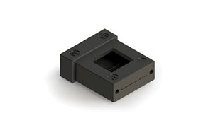
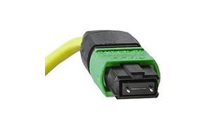
What are the differences between MT ferrules and standard connector ferrules? Unlike cylindrical ferrules which are typically for connecting single fibers, MT ferrules are designed to mate multiple fibers, greatly increasing the number of fibers that can be mated per-connection. An MT ferrule is a rectangular polymer (plastic) block with holes for multiple fibers, where typical single-fiber ferrules are ceramic, requiring different polishing processes and materials. The fiber hole spacing (“pitch”) of MT ferrules is standardized to ensure alignment with a mating ferrule. Mated-ferrule alignment is achieved with two guide pin holes molded into the MT ferrule itself.


How many holes? The answer will depend on what equipment and protocols are being used in the fiber network.
The options in MT ferrules / MPO connectors from several companies cover a range from 4 to 72 holes per ferrule. Thus, one mated pair can provide connector joints for up to 72 fibers. The number of holes in a single row can range from 4 to 16, and there can be up to six rows in one ferrule. For example, a 72-hole version on the market has six rows of 12 holes. Another example is a 32-hole product that has two rows of 16 holesi The current most commonly-used configurations are 12-hole (1 row of 12) or 24-hole (2 rows of 12).
MT ferrules and MPO connectors are available for both single-mode and multimode fibers, with the only difference being tighter dimensional tolerances on the Singlemode versions. Single-mode applications typically require a 8-degree polished MT end-face. Singlemode ferrules can be purchased as “flat” (where the cable-assembly producer will need to polish the 8-degree angle into the ferrule), or as “pre-angled”, with the 8-degree angle already generated (which reduces polishing time). Multi-mode applications typically require “flat” (non-angled) ferrule end-faces.
Making MPO-type assemblies
The presence of multiple fibers and the polymer ferrule material mean that the assembly-production processes are substantially different from those used with traditional single-fiber ceramic or metal ferrules. The main differences are in polishing: materials required; the number of steps involved; and the industry-defined finished geometries of the polished end-face. Achieving low-loss connections for multiple fibers in one mated pair is much more complicated than with single-fiber connections, further reinforcing the need to carefully follow well-established procedures to minimize quality and yield problems. In short, all challenges and difficulties in achieving good terminations are multiplied for MPO connectors.
Several vendors offer MT ferrules, and they use different polymers. The polymers’ properties have a bearing on the polishing procedures. At least three of the vendors use a variant of polyphenylene sulfide (PPS), a thermoplastic polymer. The ceramic materials used for cylindrical ferrules are more uniform among vendors, and identical or very similar polishing processes can be used for cylindrical-ferrule connectors from different vendors. For MPO connectors, there is greater variation among the procedures used by different assembly manufacturers.
All MT-ferrule polishing processes have three main objectives:
A. remove epoxy on the end-face and in some cases generate the angle, (if needed, Singlemode only);
B. one or multiple steps to generate required fiber height;
C. one or multiple steps to polish the fiber end faces while maintaining required fiber height.
The number of polishing steps needed to achieve these three objectives can vary among MPO assembly manufacturers. FOC, for example, recommends four polishing steps, one for objective (A.), one for objective (B.) and two for objective (C.). For the latter objective, FOC recommends using two polishing pads with different abrasives. Some other companies may use different abrasives and a different number of steps for objectives (B.) and (C.). In our experience, a four-step process is typical of that used by many assembly manufacturers.
Details of the polishing steps
For objective (A.), epoxy removal, and possibly angle generation, FOC recommends a 16-µm (grit size) silicon carbide disk. This is similar to the abrasive used in the first polishing step with zirconia ferrules. Regarding the angle, the assembly company has two options: order a pre-angled MT ferrule or create the angle in the first polishing step. Pre-angled ferrules reduce polishing time, and help ensure more consistent product geometries.
For objective (B.), shaping the end-face to get the correct fiber protrusion, FOC recommends a 3-µm silicon carbide polishing disk. This step differs significantly from any procedure used to make assemblies with cylindrical zirconia ferrules. With zirconia ferrules, the goal is to have the fiber end flush with the ceramic ferrule end. This is why diamond films are practical – the diamond cuts both the glass and zirconia at similar rates. In an MPO assembly, the fibers MUST protrude from the polymer ferrule end-face: the MT ferrule surface is one plane, and the fibers must protrude beyond that surface. The extent of this protrusion, or the fiber height, typically ranges from 1.5 to 4.0 µm.
Further, the goal is to have the same amount of protrusion for all the fibers, with the variation in fiber height amongst the different fibers in the hundreds of nm or tenths of a µm. The abrasive material for this polishing step must cut (mechanically etch) some of the plastic ferrule away without shortening the fiber. The 3-µm abrasive disk results in a fiber height of about 3 µm. The final polishing steps may lower this height slightly, so the procedure in this step is tailored to achieve the final fiber-height specification.
For objective (C.), polishing the fiber end faces to remove scratches, pits, and other defects, FOC recommends a two-step process, using two different abrasives. This objective is where we have seen different approaches among different assembly manufacturers, with a different number of polishing steps.
In the two-step process that FOC recommends, the abrasives are in a flocked-pile pad, not on a film. The flocked material has microscopic strands (picture a carpet, though in microscopic dimensions!), and the abrasive particles – either 1-µm or sub-micron sized – are adhered to the strands in the pile. Specifically, FOC recommends a flocked pile with 1-µm aluminum oxide abrasive for the first polishing step, and a sub-micron abrasive of either cerium oxide or silicon dioxide for the second polishing step. (The submicron pad available from FOC is called AngstromBrush Ultimas and is specially developed for polishing fiber ends in MT ferrules.)
The flocked pads are designed for use on the same glass substrates and polishing machines that are used for cylindrical ceramic ferrules. That is, the MT polishing with flocked pile pads uses the same polishing motion. The number of MT ferrules polished in a single step depends on the machine and fixtures being used. There can be more than 12 MT ferrules in one fixture. There is one important difference from ceramic polishing: all films and pads for MT polishing are to be used only one time. (Disks for ceramic ferrule polishing can be used for multiple runs; this is not true for MT abrasives.)
Summary and key tips
Producing assemblies with MPO connectors offers different challenges compared with ceramic ferrules. Below are some general recommendations from FOC’s engineers.
- When polishing MT ferrules, use films and flocked-pile pads made specifically for MT ferrules.
- MT ferrules do not all use the same material. The techniques for polishing are not as uniform as those for cylindrical ceramic ferrules. This can be a reason to stay with just one MT ferrule supplier.
- All films and flocked pads are for one-time use. This includes the first step, with 16-µm film, the second step with 3-µm film, and the final steps using flocked-pile pads. (Point being: per-ferrule polishing costs are MUCH higher for MT ferrules than for traditional ceramic single-fiber ferrules.
- Finally, we note that MT ferrules have guide-pin holes that can become contaminated, so there is a mandatory cleaning step to clean these guide holes after polishing.
MPO in the Market
MT-ferrules date back to 1986, when NTT, Fujikura, and Furukawa jointly developed this connector concept. In the 1990s, there were some niche application in datacom. After 2000, the demand for MT terminations has increased with trends in data center architectures, such as the use of higher-count cables and high-density rack configurations. Also, since 2000, demand also has increased with new applications. One example has been the development of ruggedized versions for outside-plant telecom applications, such as in distribution (local loop) networks or in cellular infrastructure (fiber-to-the-antenna).
High-count, high-density interconnects are driving very active R&D programs. In recent years, several new connector types have emerged for on-board, card-edge, and high-density rack applications. New concepts incorporating lenses for expanded-beam optical pathways have entered the market. As noted, there is also work on more holes, with a 96-fiber MPO type connector mentioned at 2020 conference. Finally, the acceptance of MT ferrules and MPO connectors is driving a large array of fan-in and fan-out products and specialized harnesses for data centers – cable assemblies with complex configurations.
At this point in 2020, we’re seeing that MPO types are continuing to capture a larger percentage of the interconnect market, in terms of the number of fiber ends mated with different connector types. As demand has increased, more companies have begun offering MPO assemblies, and there has been more R&D on MT processing. In our work at FOC, we have seen different procedures and materials being used at different companies. FOC is glad to discuss options for MT-ferrule polishing and to make recommendations based on our experience. Please feel free to contact us by phone or email for more details.
i In an October 2020 conference, YOFC of China said it had developed a 96-hole MPO-type connector. The status of this device in terms of commercial availability was not clear at the time. But the announcement illustrates the trend for connector companies to develop higher-count connectors to address requirements for high density, especially in data center applications.
This article is an original publication of Fiber Optic Center, Inc. It is shared publicly for educational and reference purposes to support learning and professional development within the fiber optics industry.
You are welcome to read, cite, or reference this material for non-commercial and educational purposes, as long as full credit is given to Fiber Optic Center, Inc. and the author.
Reuse, reproduction, or adaptation of this content — including rewriting, republishing, or incorporating it into new materials (such as websites, blogs, marketing text, technical guides, or AI-generated content) — is not permitted without prior written consent from Fiber Optic Center, Inc.
This material is protected by copyright law upon publication, even if not formally registered.
Use of this content for AI training, automated data extraction, or derivative content generation is prohibited.
Fiber Optic Center monitors and enforces the integrity of its intellectual property through digital identifiers and content tracking.
For more details, please refer to the Fiber Optic Center Content Use and Copyright policy.


