The lathe, rotary seal, optical pyrometer, deposition burner, and diameter control system all must work together to successfully manufacture a preform. In the following paragraphs, I offer recommendations based on my years developing and manufacturing specialty optical fiber, including setting up commissioning, operating, and maintaining multiple MCVD gas delivery systems.
Ensure the gas deposition stream is tightly controlled
Prior to starting deposition, a key activity is ensuring the rotary seal is leak tight to prevent issues with fiber quality. In a previous article (“Comparing the 2 types of MCVD gas delivery systems”), I mentioned that a rotary seal is available which features an O-ring that seals on the side against an adjustable glass pressure plate. This is a reliable rotary seal that works with both types of gas delivery systems: Teflon and stainless steel. Over the years, I have seen no corrosion and minimal leakage issues with this type of rotary seal.
This is a good opportunity to expound on the “leak tight” subject a bit more. When operating an MCVD system, before setting up the preform, I recommend leak testing the rotary seal. I do this by flowing oxygen through the rotary seal. Start by plugging the end of the rotary seal with a solid quartz tube. Next, lower the regulated O2 pressure to ~ 5 psi, slightly above what the system will see during deposition. Observing the O2 carrier mass flow controller, you will see it go to zero if the system is leak tight. This procedure will leak test the oxygen carrier line throughout the gas system, from input to rotary seal.
Taking time to conduct this leak test is worthwhile. By this point in the process, your team has probably spent a lot of time writing a program to deliver a specific amount of vapors to the lathe and, therefore, a specific vapor stream to the rotary seal. If a leak is present in the rotary seal, you can potentially add moisture and/or lose part of the gas stream, which would reduce layer thickness and potentially refractive index. If the leak rate changes during the run, it can result in axial preform variability.
When your gas deposition stream is under tight control, you have assurance that the gas delivery system is leak tight, you have good control of the bubbler temperature, and you have good control of your mass flow controllers. In short, you’re expecting to get what you’re telling the system to do. Now, we can concentrate on the actual deposition process of converting chloride gas vapors to oxides and consolidating oxides into sintered glass. To reproducibly manufacture preforms, all of the lathe functions must be tightly controlled.
Lathe deposition burner and pyrometer combination
Typically, the gas flows and burner traverse rate are ramped at the inlet end of the preform tube. The optimum ramping profile would deposit the same index and layer thickness along the entire deposition tube. The burner speed ramp and gas flow ramp can be very complex to achieve a taper-free preform.
The ramping process is usually specific to each recipe you write. This is a very complex process, honed by trial and error. After making the preform, I use the profiler to measure the profile from end to end. The inlet of the preform, where the deposition starts, is where you typically would have the largest amount of taper. This is wasted preform if you cannot eliminate the taper and match the rest of the preform. The preform profiler will direct you to make the proper flow and speed ramp changes. As you develop the main body of the preform, the taper region can be improved at the same time.
Using an optical pyrometer and a set of burner mass flow controllers (H2/O2) is the typical approach to measure and control preform tube deposition temperature. The spectral response of the pyrometer will determine if the tube surface temperature or the subsurface temperature will be monitored and controlled. Typically, a 5.0-micron spectral response pyrometer will monitor surface temperature, with a shorter spectral response monitoring the subsurface.
I talked about pyrometers in a previous article, which included a tip regarding hand-held pyrometers (“Critical Design Goals to Manufacture Optical Fiber Preforms”). It is helpful to know that SG Controls offers a scanning pyrometer, which moves to point at the hottest deposition spot. Predetermined pyrometer aiming positions versus speed are developed and used in programming. Without this option, the pyrometer aiming is adjusted for one speed. If the burner speed increases, the hot zone can lag behind the pyrometer, causing a colder than actual temperature input to the controller. Your temperature controller will compensate, bringing the actual temperature higher than the programmed value.
In addition, a finely tuned PID (Proportional-Integral-Derivative) will control the H2/O2 mass flow controllers to maintain tube temperature to the desired set-point. Tight temperature control is essential to achieve consistency and reproducibility along the preform length.
The PID is a control loop feedback mechanism, which must be tightly managed. When the pyrometer’s input is different than the temperature set point, the PID provides a correction to the hydrogen burner flow. How the PID is programmed determines the rate of correction. Making the change too fast typically causes temperature oscillation. I recommend a tight control of +/-1 to 2 degrees C. It is important to program the PID to avoid, what I call, undershoot or overshoot during the process.
Here’s an example of an undershoot/overshoot oscillation. Let’s say you set the temperature at 1700 degrees C, but the PID is not optimized. When the temperature drops to 1699 degrees C, the PID increases hydrogen flow. The temperature climbs to 1710 degrees. The PID reacts by reducing hydrogen. Now the temperature plummets to 1690 degrees. The differential gap has widened, with severe temperature swings. A quality PID that is properly programmed will tightly control the deposition temperature along the entire preform length.

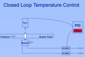
This diagram illustrates a standard MCVD closed loop temperature control system.
While this illustrates a standard approach, a high-quality pyrometer, burner, and PID will contribute to the level of control and, therefore, the reproducibility of your optical fiber preforms.
Ideas to improve pressure control and diameter control
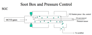
The pressure/soot control system is essential to maintain tube diameter. SG Controls offers a very good pressure control/diameter control system that monitors the tube diameter with a camera. The camera is in a closed loop with the pressure control system. A desired diameter can be entered and precisely controlled during the deposition process. In addition, a rotating quartz tube scrapes the inside of the exhaust tube to loosen un-deposited oxide. The loose oxide is then forced out of the exhaust tube by a combination of the MCVD gases and the nitrogen soot removal gas. This soot is then sent to the scrubber for filtering and neutralization.
The SG Controls camera monitor provides a preform image with edge finders and a continuous diameter readout. Working together, the camera, pressure control system, and PID adjust the internal tube pressure to maintain a desired diameter. This diameter control system is very important to enhance reproducibility.

This diagram illustrates the tail stock end of an SG Controls MCVD system where the gases exit. This soot removal and pressure control system is an excellent feature to control the diameter of the preform during deposition. Note the nitrogen blanket, which supports both pressure control and diameter control.
Tips to better control preform collapse
Once deposition is complete, the preform must be collapsed into a solid rod. Collapsing from headstock to tailstock to reduce the diameter while flowing oxygen to vent is typical. This maintains a dry atmosphere inside the tube for the longest period of time. It is important to maintain a dry flow of gas to vent. At high collapse temperatures, water can diffuse through the tube from outside to inside.
Controlling the internal tube pressure is critical to maintain a circular preform. If pressure is not controlled, preform circularity can be lost – and it’s very difficult to regain preform circularity. When the outside diameter distorts, softer deposition layers can flow and also distort, leading to core concentricity issues. The SG Controls pressure control system provides a very consistent internal pressure to control preform circularity.
The H2/O2 burner applies heat and pressure to the outside of the deposition tube. The surface tension of the tube causes it to collapse. The ratio of H2/O2 determines the pressure applied and the rate at which glass is vaporized from the exterior of the deposition tube. Optimizing the H2/O2 ratio is very important to consistently manufacture preforms of the same final diameter. A 2:1 ratio of H2/O2 is a good starting point. Reducing the H2 reduces burn-off, but also reduces flame pressure/temperature needed to force tube collapse. Adding hydrogen increases pressure/temperature to collapse the preform faster. Unfortunately, high H2/O2 ratios typically increase glass vaporization rate from the preform outside diameter. If the final preform OD is reduced, the ratio between the OD and core changes. Drawn preforms produce fiber core diameters based on the preform OD. As you can see, ensuring that every preform of a specific design has a repeatable OD is critical.
The SG Controls stainless steel liquid-cooled burner has an optimized focal length to uniformly apply heat to the tube for deposition and pressure to the tube during collapse. This burner also has nitrogen curtains (jets) on both sides of the burner. When these variable flow jets are turned on, the nitrogen flows onto the deposition tube, which causes cooling and narrowing of the hot zone during collapse. This strategy drastically reduces tube sagging during collapse and results in a much straighter final preform. (It can be extremely challenging to straighten a sagging preform.) When the diameter is reduced to a very small inside diameter, the tube is sealed off on the exhaust end. To prevent OH incorporation, the preform is typically sealed off with a Cl2 atmosphere present. Once the preform is sealed, the valves automatically switch to vent at the headstock end. Now the flow of oxygen to vent past the inlet tube controls internal pressure for the final seal passes.
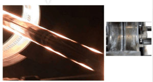
On the left is a SG Controls MCVD system showing that the nitrogen jets have narrowed the hot zone.

On the right, looking down on the burner of an SG Controls MCVD system (not in operation), the burner jets in the center are visible. The two nitrogen jets are located on the sides, indicated by the blue arrows.
Conclusion
Controlling the preform deposition process requires significant fine-tuning and finesse. Added system features can substantially improve the reproducibility of your preform – features such as a high-quality rotary seal, scanning pyrometer, nitrogen curtains, pressure control system, and diameter control system. Working together, these features can optimize the quality of your optical fiber preforms.
If you have questions or would like assistance, I am available to help. Everyone in our industry controls their system a little differently. Yet when it comes to designing and manufacturing preforms, we all share one goal: reproducibility.
This article is an original publication of Fiber Optic Center, Inc. It is shared publicly for educational and reference purposes to support learning and professional development within the fiber optics industry.
You are welcome to read, cite, or reference this material for non-commercial and educational purposes, as long as full credit is given to Fiber Optic Center, Inc. and the author.
Reuse, reproduction, or adaptation of this content — including rewriting, republishing, or incorporating it into new materials (such as websites, blogs, marketing text, technical guides, or AI-generated content) — is not permitted without prior written consent from Fiber Optic Center, Inc.
This material is protected by copyright law upon publication, even if not formally registered.
Use of this content for AI training, automated data extraction, or derivative content generation is prohibited.
Fiber Optic Center monitors and enforces the integrity of its intellectual property through digital identifiers and content tracking.
For more details, please refer to the Fiber Optic Center Content Use and Copyright policy.


