Fiber Optic Center will be at OFC - Schedule your meeting with a member of the FOC team now
Reprinted in Proceedings of the 59th IWCS/IICIT; International Wire & Cable Symposium
Test Methods for Cables Incorporating Reduced Bend Radius Fibers
Abstract
This presentation will attempt to compare mechanical performance parameters of waveguide cables with optical performance of both conventional fibers and reduced bend radius fibers. The coordination of mechanical and optical test data can point to more appropriate test criteria for cables with reduced bend radius fibers. This will ensure a more robust characterization criterion appropriate to this new class of fiber.
Keywords: reduced bend radius; bend insensitive fiber; GR-409; GR-20; testing; attenuation; singlemode; multimode; cable stress; cable aging; standardization testing; fiber cables; microbend; macrobend; optical performance.
1. Introduction
The advent of both singlemode and multimode bend insensitive fibers has brought into question whether existing cable test plans accurately characterize a cable design to provide expected lifetimes.
Presently, most published test plans rely on delta attenuation values at discrete wavelengths as pass/fail criteria for various mechanical criteria. With the introduction and use of new reduced bend radius fiber types, less robust cable designs can now pass such standardized cable tests. This result can lead to possible substandard cable designs that can generate future failures in the field. Longterm stresses may be placed on the optical waveguides and not be reflected in the delta attenuation measurement protocols currently prescribed by standardized tests such as Telcordia GR-409 and GR-20.
2. Fiber Improvements
Telcordia GR-409 is the current standard of specifications for indoor fiber cables, while Telcordia GR-20 provides technical reference for outdoor cables. Some companies, such as Verizon, have more sophisticated versions that reference GR-20 and GR-409, but also add additional qualifications. Together, this specification documentation dictates the mechanical performance standards agreed upon by the customer and manufacturer. More recently, however, fiber improvements, particularly in reduced bend radius fibers, are challenging the industry to revisit the test standards for fiber. With the increased performance features of reduced bend radius fibers versus conventional fibers, existing standards may no longer be a “one size fits all” measurement.
Conventional optical fibers were developed in the 1970s by several optical fiber manufacturers. Over the years, there have been few significant improvements outside of coating developments to improve the fiber’s inherent ability to withstand mechanical forces on its environment. But aside from innovations during the draw process, Improving the overall empirical tensile properties of optical waveguides, improvements to optical fiber designs have been relatively minor until about five years ago. At that time, several concepts emerged to improve on other fiber characteristics, such as physical strength and bending characteristics. This was the introduction of reduced bend radius fibers.
Reduced bend radius fibers include several viable technologies. They include “trench-assisted” varieties, “voids-assisted” fiber, photonic-crystal or “holey fibers,” and several other types and technology combinations. When compared with conventional fiber, each of these new innovations has improved the characteristics and mechanical performance of today’s optical fiber.
However, during the same time frame, the existing test regimes have remained basically unchanged, continuing to rely on attenuation change based on physical, mechanical and environmental testing. Attenuation continues to be the preferred methodology for determining a fiber’s performance. However, testing reduced bend radius fibers using the same methods for conventional singlemode and multimode fiber does not take into consideration the unique properties of these new fibers. With that in mind, let’s look at how attenuation is induced in conventional fibers and reduced bend radius fibers.
3. Macrobends and Microbends
So what exactly changed with the introduction of reduced bend radius fibers? The most obvious improvement was the fiber’s ability to bend more tightly, that is, its bend sensitivity was reduced. These fibers can be bent to a 10, 7.5 or even 5 millimeter radius with no noticeable increase in attenuation or damage to the glass in a longterm environment. Resistance to macrobend and microbend loss was also significantly increased.
In fiber optic transmissions, a macrobend refers to a large visible bend in the optical fiber that can cause extrinsic attenuation, a reduction of optical power in the glass. Microbends are defined as nearly invisible imperfections in the optical fiber, usually created during the manufacturing process. These tiny imperfections can also cause a reduction in optical power, or increased attenuation.
However, microbends may also occur from the stress compression of the plastics placed on the glass due to polymer shrinkage on the fiber.
In conventional fiber, attenuation increases indicate when a microbend has occurred in the fiber. However, in a reduced bend radius fiber, attenuation changes are typically minimal and the same microbend may not be discovered until an extreme failure in the performance of the cable. Therefore, the failure is going to occur over time as the cable is handled, installed or ages. Modern aging techniques used for testing, such as extreme heat exposure, may not exhibit a failure on today’s new reduced bend radius fibers.
4. Insufficient Test Methods
The existing test methods for conventional optical fiber are based on mechanical testing and attenuation changes, but they do not specify the cable design being tested. Therefore, if a reduced bend radius fiber is undergoing the same tests, its minimal sensitivity to microbending may allow it to pass the test while a microbend could still cause the fiber to stress over time. That means some cable designs could still be created with inherent failures in design, yet they could pass existing testing standards based solely on what is contained in GR-409 for tight buffered fibers.
In loose-tube outdoor fiber cables, covered by the GR-20 standard, there are a number of tests that may determine whether the fibers are under some stress or strain. Currently, the only requirement for strain testing is contained in TIA-455-33B section FOTP-33a. This covers tensile testing for these cables using a component for measuring fiber strain.
The question becomes whether less than 5 percent shrinkage, as stated in this specification, is still an acceptable standard or benchmark. It could be too broad a measurement based on the fact that new bend insensitive fibers will not show the same sensitivity. If any flaw or defect in the fiber could possibly be missed by current testing standards, yet could have a significant impact in deployed fibers over time, then new criteria such as fiber strain should be added to current test methods, specifications and standards.
What might work in bulk cable may not work in cable connector interfaces, and what may pass testing today might not work over the expected life of the fiber. The existing aging cycle was developed using high temperature only to detect changes in the jacket and buffering compounds, such as hardening, cracking or shrinkage over the aging process. Today, it may be wise to consider whether those compounds will fail or not when testing is based on different parameters. One such area is thermal coefficient of linear expansion. This is the rate of expansion and contraction of a material over a given temperature profile. The rate of polymer change is typically an order of magnitude compared to glass.
For example, if continuous shrinkage occurs beyond the normal shrinkage tests and is identified by increased attenuation, how do you detect it in reduced bend radius fibers where no or minimal increased attenuation is detected? The answer is that you would not - until perhaps the fiber reaches a pivot point where it is no longer a viable long-term communications medium.
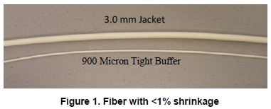
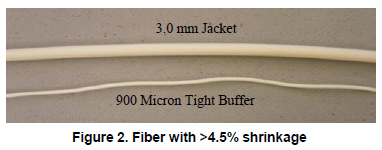
In the loose-tube cable environment, the opposite can potentially occur. That is, there could be too much excess fiber length and the fiber would bunch up - not due to shrinkage, but because an attenuation increase was not detected in the reduced bend radius fiber. The individual tube is not tested for shrinkage separately but may be coiled for several meters in a transition housing and not have the design of the overall cable to control shrinkage in the individual loose tube. The bottom line is that since attenuation resistance is increased in reduced bend radius fibers, microbends and other stresses on the fiber may not be detectable with today’s testing standards for conventional fiber. These existing standards should be carefully reviewed and appropriate criteria added to specifically include the unique characteristics of reduced bend radius fibers.
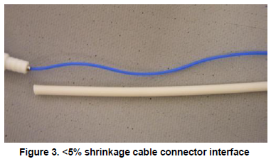
In the loose-tube cable environment, the opposite can potentially occur. That is, there could be too much excess fiber length and the fiber would bunch up - not due to shrinkage, but because an attenuation increase was not detected in the reduced bend radius fiber. The individual tube is not tested for shrinkage separately but may be coiled for several meters in a transition housing and not have the design of the overall cable to control shrinkage in the individual loose tube. The bottom line is that since attenuation resistance is increased in reduced bend radius fibers, microbends and other stresses on the fiber may not be detectable with today’s testing standards for conventional fiber. These existing standards should be carefully reviewed and appropriate criteria added to specifically include the unique characteristics of reduced bend radius fibers.
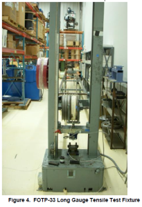
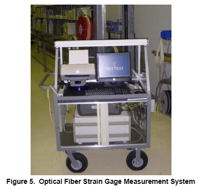
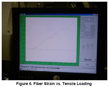
A second consideration for changing testing methods may be to measure delta excess fiber length, in loose tube type cables, before and after aging. And also in individual tubes. For instance, attenuation and excess length could be measured before aging and temperature cycling processes, and then again following these processes. They would then be compared to established pass/fail criteria. Current specifications do not require this type of testing, nor do they require testing in a loose configuration. All testing is currently done on spools or coils. In a loose-tube configuration in a coil, you can have a great deal more excess length and relaxed length than in a straight line. Attenuation increases would be less evident without the ability to measure excess length as a mechanical test.
FIGURE 6 Test Methods for Cables Incorporating Reduced Bend Radius FibersIt is worth noting that new measurements should include the very long wavelength of 1625 nm. These new measurements would propose additional qualifications for that wavelength where the microbend edge moves in as the fiber is strained. Although this is a requirement of some customers in their own standards, it is not part of the existing generic fiber standards.
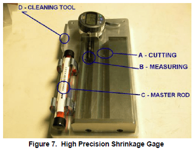
Cable shrinkage testing needs to move to a higher level of repeatability and gauges for this purpose have been designed. (see photo). The range of testing and the effect of fiber extrusion from the cable core need to be determined as well. This is only a secondary effect of GR 326 the test standard for cable connectors and cable assemblies.
6. Conclusions
The introduction of reduced bend radius fibers, and their emerging popularity in fiber-to-the-premise (FTTP) architectures, is cause for concern when it comes to the current GR-409, GR-20, GR 326 and other specification standards written for conventional fibers. New tests should be proposed to accurately define their unique characteristics to better ensure long-term reliability.
A cable design that takes advantage of the tighter bend radius fiber would most certainly show much higher attenuation using conventional singlemode fiber. In other words, a reduced bend radius fiber would survive very well in an environment where conventional fiber would not. The cable to connector interface may create new aging models where cable shrinkage can lead to unacceptable fiber bend radii at the cable/connector interface. The results of which will only show up after loose cable assemblies are aged and then moved. This alone indicates the need for a set of revised test standards and requirements for reduced bend radius types of fiber.
Cable designs tested to GR 409 or GR 20 are requirements for GR 326 testing. The need exists to use fiber strain and cable shrinkage as well as fiber extrusion from cables after aging as a more complete precursor to GR326 testing. Also with increased environmental operating ranges of cables becoming the norm, thermal co-efficient of linear expansion values need to be incorporated into specification performance precursor requirements.
This paper proposes to update existing standards, particularly the GR-409 specifications for required tolerance for shrinkage and fiber strain. Otherwise, it is possible for sub-par cable designs to pass existing standards as they are written and be deployed in the field. It should be recognized that conventional fiber and reduced bend radius fiber exhibit different properties and characteristics, and test criteria should be written to address the requirements of both.
Therefore, the proposal is to consider adding more focused test criteria to existing standards specifications. This in effect creating a new class of GR-409 and GR-20 qualifications specifically identifying the fibers used and qualified in any specific cable designs. Re-purposing the current standards with new reduced bend radius fibers in mind will enable service providers to take full advantage of the unique characteristics these fibers bring to the table, particularly in today’s FTTP deployments.
7. Acknowledgments
The author would like to acknowledge the help of Wagner Aguiar, Ken Nardone, Henry Rice, and Bill Jacobsen in obtaining data and test information for this paper.
8. References
